


Options
13
6.0 OPTIONS
This section discusses the options available for the STS2. The communications options are also dis-
cussed in 12.0 - Communication Interfaces.
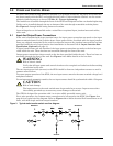
6.1 Programmable Relay Board
The Programmable Relay Board (PRB) provides a means to trigger an external device when an event
occurs in the STS2. Each PRB has 8 channels. Each channel has two sets of Form-C dry contacts,
rated 1 Amp @ 30 VDC or 250 mAmp @ 125 VAC.
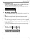
Any alarm/event can be programmed to any channel or channels. Up to ten (10) events can be pro-
grammed to a relay. If multiple events are grouped to one relay, group the events logically to simplify
troubleshooting when an event is triggered. The same alarm/event can be programmed to more than
one channel. Up to two Programmable Relay Boards can be installed in the STS2 for a total of 16
channels. Programming is performed through the touch screen display.
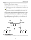
See Configuring the Programmable Relay Board Settings on page 97 for default settings and
instructions for reconfiguring the relays. See Figures 21 and 22 for the location of the PRB. See
Figure 24 for wiring details. Table 8 provides the PRB pinout.
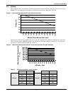
6.2 Optimized Transfer
When the STS2 is used as a primary-side switch—on the primary of an isolation transformer—opti-
mized transfer greatly reduces the transformer magnetization current during automatic transfers
through a new transfer control algorithm. The Liebert algorithm (patent pending) optimizes the
transfer timing so that the volt-seconds applied to the downstream transformer primary is balanced,
minimizing peak saturation current.
The volt-second balance is achieved by directly computing the volt-second applied to the transformer
during transfer events and determining the optimum time to turn on the alternate source SCRs in
order to balance the volt-second within specified tolerance.
Optimized transfer also seeks to minimize the voltage disturbances while still maintaining trans-
former flux balance. This unique flux balance algorithm does not just wait for the balance point to
occur, but will pulse fire the SCRs as soon as possible to minimize the voltage disruption. This results
in far superior voltage waveforms applied to the load.
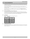
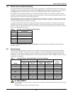
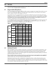
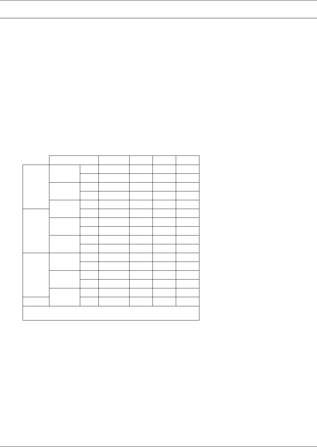
Table 8 Programmable relay board pinout
Channel Pin No. C N.C. N.O.
TB1
CH1
A1-3 1 2 3
B4-6 4 5 6
CH2
A7-9 7 8 9
B 10-12 10 11 12
CH3
A 13-15 13 14 15
TB2
B1-3 1 2 3
CH4
A4-6 4 5 6
B7-9 7 8 9
CH5
A 10-12 10 11 12
B 13-15 13 14 15
TB3
CH6
A1-3 1 2 3
B4-6 4 5 6
CH7
A7-9 7 8 9
B 10-12 10 11 12
CH8
A 13-15 13 14 15
TB4 B1-3 1 2 3
Key: N.O. = Normally Open; N/C. = Normally Closed; C = Common
Note: Pin 16 not used on TB1, TB2, and TB3.