


Power and Control Wiring
9
5.0 POWER AND CONTROL WIRING
All power and control wiring should be installed by a qualified electrician. All power and control wir-
ing must comply with the NEC and applicable local codes. Unless otherwise labeled, use the recom-
mended tightening torque as shown in Table 25 - Torque tightening.
The busbars are accessible through the front of the STS2 and designed to allow one-handed tightening.
Cables can be installed through the top or bottom of the unit through removable conduits plates.
See Figures 5 through 10 for wiring entrance locations.
Input wiring also can be installed under a raised floor to optional input junction boxes and cables,
when used.
5.1 Input And Output Power Connections
If the unit is furnished with input junction boxes, the input power connections are made to the input
power terminals located in the junction boxes. Input power cables, furnished with the input junction
boxes, are shipped unattached to the unit for connection between the junction boxes and the bus bars
provided inside the unit. Input junction box installation is discussed in 5.2 - Input Junction Box
Installation (Optional) on page 10.
If input junction boxes are not furnished, the input power connections are made to the bus bars pro-
vided inside the unit. These bus bars are accessible through the front of the unit.
Output power connections also are made to the bus bars provided inside the unit. These bus bars are
accessible through the front of the unit. See Figures 14 to 19 for details on the bus bars.
The two input power feeds (sources) to the STS2 should be from two independent sources to avoid a
common source failure.
To ensure proper operation of the STS2, the two input sources must be the same nominal voltage level
and phase rotation.
For uninterrupted automatic transfer, the two input sources should be synchronized within 15 degrees.
The STS2 is designed for operation with 3 or 4-wire solidly grounded sources only.
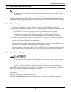
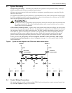
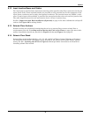
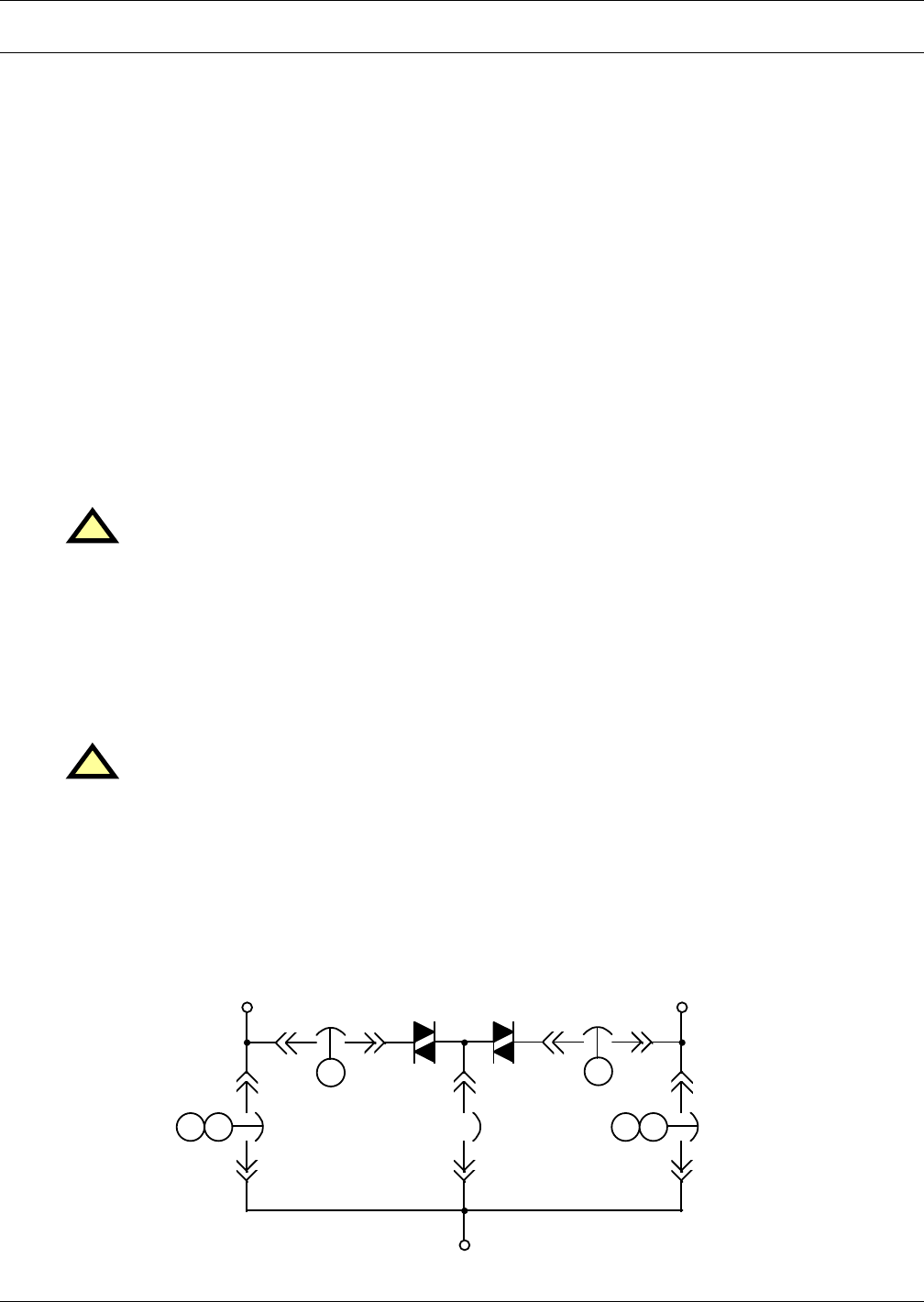
For 4-wire operation, the common source neutral must be connected to the STS2. See Figure 3 on
page 9 for a typical one-line diagram. Refer to Figures 14 to 19 for electrical field connections on all
units, with both single and dual output breakers.
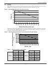
Figure 3 Typical static transfer switch one-line diagram
!
WARNING
Risk of electric shock
Verify that all input power and control circuits are de-energized and locked out before making
connections inside unit.
!
CAUTION
Risk of unit damage.
The input sources to the static switch must be grounded-wye sources. Input sources other
than solidly grounded-wye sources may cause damage to the switch.
SOURCE 1 SOURCE 2
STS1 STS2
CB1 CB2
CB3 CB5CB4
OUTPUT
K1
K2
K3K2 K3K1
SS1 SS2