


Options
15
6.7 Network Interface Card (NIC)
An OpenComms Network Interface Card (NIC) enables the STS2 to communicate to a network man-
agement system (NMS). The NIC provides the internal hardware and software to communicate, via
SNMP, to any I.P.-based Ethernet network through an RJ-45 connector using Category 5 cabling.
The NIC provides redundant paths for communications that make it possible to connect to a Building
Management System (BMS) using Modbus, while simultaneously communicating to a NMS through
SNMP. A terminal block provides the connection to Modbus.
See Figures 21 and 22 for the location of the NIC.
See Figure 28 control wiring information.
If you have questions about the NIC, refer to the OpenComms Network Interface Card Installation
and Users Guide.
6.8 LED Display
A light-emitting diode display is available to replace the standard liquid crystal display touch screen
control. The display provides monitoring and control throuh a series of LEDs and buttons. LEDs alert
you when a problem occurs. A PC running terminal emulation solfware conneted to the RS-232 port is
needed to access the data and configuration settings.
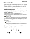
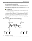
6.9 Remote Source Selection
The Remote Source Selection allows the preferred input source to be chosen from a remote location. A
user supplied normally open dry contact allows the user to remotely select a source to be the preferred
source in the same process as the local source transfer selection.
The unit’s preferred source selection and Remote Source Selection are active at the same time, with
the STS2 following the last request for a preferred source change, regardless of whether it was from
the local or Remote Source Selection controls.
See 10.3 - Enabling Remote Source Selection for instructions on enabling the Remote Source
Selection.
See Figures 21 and 22 for the location of the Remote Source Selection option.
See 5.5 - Remote Source Selection Wiring on page 12 and Figure 23 for information on the con-
trol wiring.
6.10 Key Lockout Switch
The key lockout switch activates a software lockout of the touch screen display to prevent manual
transfers and configuration changes. When locked out, the touch screen becomes a read only display.
A key is needed to do manual transfers or change settings.
The alarm silence button is not disabled when in the lockout position.
The switch is located behind the front door but can be operated without opening the front door. See
Figures 8 to 10 for the key lockout location on each unit.
See 14.1.4 - Key Lockout Switch for instructions on using the key lockout switch.
6.11 Redundant Output Breaker
An output plug-in, non-automatic circuit breaker is provided which allows redundancy in the output
power path. The breaker is connected in parallel with the output plug-in non-automatic circuit
breaker.