


Alarm and Faults
74
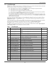
11.4 List of Messages
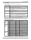
Table 9 lists available event messages, a definition of the event, and the functions that are activated
with the event by default. The functions are indicated as follows:
D — The indicated event initiates the Auto-Dial sequence through the optional modem.
A — The indicated event activates the Audible alarm.
F — The indicated event triggers a Freeze of the History Log.
L — The indicated event Latches. A latched alarm remains displayed until the alarm condition
has cleared and the RESET (ALRMRST) button has been pressed.
E — By default, all faults and alarms are written to the Event Log. Changing this setting is only
available for the LED units and is set through the RS-232 port. See Setting Event Masks with
the Terminal on page 83
All of these functions, except Freeze, can be reconfigured to trigger for each event, using the Event
Mask option. See 11.1 - Event Mask on page 71. The Freeze function is hard-coded and cannot be
changed for a event.
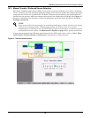
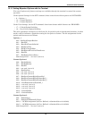
If the front panel of your STS2 contains LEDs and push buttons instead of the touch screen interface,
you can view these messages via the RS-232 port. See 12.1.1 - Connecting and Using a
Terminal on page 77 for the commands to view the event messages on a PC terminal.
An LED is used to indicate the presence of any active fault or alarm. Refer to 14.0 - Operating the
LED Display STS2 for more information about the LEDs.
.
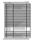
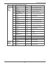
Table 9 Event Messages
ID Alarm Message Description/Cause Action
001 S1 SCR SHORT One or more of the SCRs for Source 1 have shorted and
failed.
D, F, A, E
002 S2 SCR SHORT One or more of the SCRs for Source 2 have shorted and
failed.
D, F, A, E
003 S1 SCR OPEN One or more of the SCRs for Source 1 is open. D, F, A, E
004 S2 SCR OPEN One or more of the SCRs for Source 2 is open. D, F, A, E
005 PRIMARY FAN FAIL A primary cooling fan has failed and the unit is now being
cooled by a secondary fan, which is not monitored.
D, A, E
006 CONTROL MODULE FAIL Control logic module has failed. D, A, E
007 PWR SPLY DC A FAIL Power supply DC bus A has failed. D, A, E
008 PWR SPLY DC B FAIL Power supply DC bus B has failed. D, A, E
009 PWR SPLY S1 AC FAIL Power supply Source 1 AC has failed. D, A, E
010 PWR SPLY S2 AC FAIL Power supply Source 2 AC has failed. D, A, E
011 PWR SPLY LOGIC FAIL A power supply module has failed. D, A, E
012 OUT VOLT SENSE FAIL The output volt sense module failed D, A, E
013 S1 VOLT SENSE FAIL The Source 1 volt sense module failed. D, A, E
014 S2 VOLT SENSE FAIL The Source 2 volt sense module failed. D, A, E
015 S1 SCR SENSE FAIL The Source 1 SCR sense module failed. D, A, E
016 S2 SCR SENSE FAIL The Source 2 SCR sense module failed. D, A, E
017 S1 CURR SENSE FAIL The Source 1 SCR current module failed. D, A, E
018 S2 CURR SENSE FAIL The Source 2 SCR current module failed. D, A, E
019 S1 GATE DRIVE FAIL The Source 1 gate drive module failed. D, A, E
020 S2 GATE DRIVE FAIL The Source 2 gate drive module failed. D, A, E
021 INTERNAL COMM FAIL Internal CAN communications failed. D, A, E
022 EXTERNAL COMM FAIL Options CAN communications failed. A, E
023 CB1 SHUNT TRIP FAIL CB1 shunt trip failed. A, E