


Communication Interfaces
76
12.0 COMMUNICATION INTERFACES
The STS2 monitoring system offers several choices for communications.
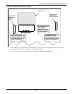
The RS-232 terminal port is standard on all units. The port is located inside the front door, to the left
of the touch screen/LED front panel mounting as shown in Figure 29. This port is primarily used as
an alternate user interface to configure, control, and diagnose the system, especially for systems that
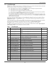
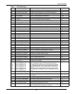
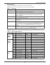
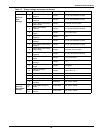
do not include the HMI touch screen. Commands for the RS-232 port are shown in Table 10.
Several other communications options are also available. Those options are located a Communica-
tions compartment to the right of the touch screen/LED front panel and are accessible when the front
panel door is open. See Figures 21 and 22 for the location of the communications options.
Connections to the communication ports are made by wiring to terminal boards located in the Com-
munications compartment. The communications options listed below reference the control wiring
drawing for each option.
• Internal modem (optional) — the connection to this modem is through a standard RJ-11 port. This
port automatically dials the programmed telephone number when a designated alarm occurs.
Automatic dial attempts are made to the first phone number at periodic intervals for 30 minutes.
After that time, auto dial attempts are made to the second phone number at periodic intervals for
the next 30 minutes. The process is repeated until a successful connection is made. Upon success-
ful connection, the system transmits the status information and then hangs up. System status
and history information can be requested and date and time can be changed through the modem.
The modem commands are shown in Table 10 on page 77. See Figure 27 for more information on
the internal modem.
• Network Interface Card (NIC) (optional) — the NIC provides connectivity to any TCP/IP-based
Ethernet network to allow the device to communicate with network management systems (NMS)
via SNMP. Events can be transmitted to the NMS to provide remote status monitoring, plus fault
and alarm detection. The NIC includes an RJ-45 port for an Ethernet connection, via Category 5
cable.
The NIC can also integrate the system with an existing Building Management System (BMS) or
out-of-band monitoring, using Mobus, a standard multi-drop protocol. The NIC has redundant
communication paths that make it possible to connect to a BMS using Modbus while simulta-
neously communicate to a NMS through SNMP
See Figure 28 for more information on the NIC. If you have questions about the NIC, refer to the
OpenComms Network Interface Card Installation and Users Guide.
• Input Contact Isolator (ICI) Board (optional) — provides an interface for up to eight user inputs.
External messages and alarms can be routed to the unit, via the ICI.
See Configuring the Input Contact Isolator Settings on page 95 for instructions on config-
uring the connections. See Figure 25 for wiring details.
• Programmable Relay Board (PRB) (optional) — up to two PRBs can be installed in the STS2 to
route STS2 events to external devices.
See Configuring the Programmable Relay Board Settings on page 97 for default settings
and instructions for reconfiguring the relays. See Figure 24 for wiring details.
• Comms Board (optional) — includes a terminal block to provide a DTE connection to an external
modem. This board also provides a direct connection to a SiteScan terminal, via an RS-422.
SiteLink-12 or SiteLink-4 is required for SiteScan to communicate with the STS2. See Figure 26
for wiring details.
Data link requirements are Full Duplex Asynchronous RS-232 format.
Communications options are also discussed in 6.0 - Options.
12.1 Using the RS-232 Port
The RS-232 port is configured with a baud rate of 9600 with 8 Data Bits, 1 Stop Bit, No Parity, and no
hardware handshaking.