


Theory of Operation
61
9.1.4 Emergency Transfer
To ensure that power remains connected to the load, the STS2 automatically performs an emergency
transfer from one input source to the other when an outage occurs on the existing source. The auto-
matic transfer takes place if the other source’s voltage is within acceptable limits, and regardless of
the phase difference between the two sources.
Emergency transfers occur with a loss of power on the output of less than 4 ms.
Emergency transfers from the alternate source to the preferred source are not affected by the Auto
Retransfer Enabled/Disabled or Retransfer Delay user settings.
9.1.5 Load Current Transfer Inhibit
The STS2 senses the load current. If the load current exceeds the preset level deemed to represent a
load inrush or fault condition, the unit’s logic disables manual and automatic transfers, even if the
selected source’s input voltage is outside the acceptable limits. This event triggers an I-Peak alarm. If
so configured, the Load Current Transfer Inhibit is automatically reset after the current and voltage
return to within normal parameters. This reset provides continued protection against a source fail-
ure. The Load Current Transfer Inhibit also can be programmed to require a manual reset. See
step 14. on page 92 under the Source Set Points heading for details.
9.1.6 SCR Failure
The STS2 continuously monitors the status of the SCR switching devices for proper operation. In the
event of a shorted SCR on the input source powering the load, the STS2 automatically triggers an
alarm and trips open the other source isolation breaker. In the event of a shorted SCR on the other
input source, the STS2 automatically triggers an alarm and trips open the other source isolation
breaker.
In the event of an open SCR, the switch automatically triggers an alarm and transfers the load to the
other source. All open and shorted SCR alarm conditions are latched and require the system to be
repaired and reset to restore normal operation.
9.1.7 On/Off Sequence
The STS2 contains no master On/Off push button control. When connected to the input sources, the
unit’s logic power comes on automatically. The touch screen display (if so equipped) is active as long
as at least one input source is energized and the Control Power Disconnect (located inside the static
switch) is on.
9.2 Detailed Component Description
9.2.1 Controls
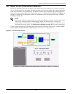
Operator Interface
The STS2 Color Graphical Display unit contains a touch screen color LCD to provide the operator
interface to control and configure the operation of the unit and quickly diagnose problems. A pass-
word and an optional keylock, if installed, are provided for security.
The LED Display unit includes push-buttons for source transfer, alarm reset and audible alarm
silence.