


Location Considerations
6
3.0 LOCATION CONSIDERATIONS
The STS2 should be placed in a clean, cool and dry location. The STS2 requires only front access for
installation and maintenance. Back or side access is not required. Adequate space is required above
the unit for conduit (if configured as such) and cooling air flow. This section provides specific informa-
tion for these considerations.
The unit is designed with top and bottom cable terminations to allow maximum flexibility in its
installation. If bottom cable entry is used, sufficient cable bending space must be provided by a raised
floor or a floor stand.
For dimensions of each unit, see Figures 5, 6 and 7 in section 7.0 - Installation Drawings on
page 17. If your unit is equipped with an optional key lockout switch, see Figures 8 through 10 for
location of that switch.
3.1 Recommended Minimum Service Clearances
The recommended service clearances are at the front of the unit. The minimum service clearance
required by the National Electrical Code (NEC) Article 110-26 is 36 in. (91 cm) for units with voltages
up to 150 volts to ground and 42 in. (107 cm) for units with voltages over 150 volts to ground. Clear-
ance of at least 18 in. (46 cm) is required above the unit for cooling air flow.
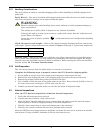
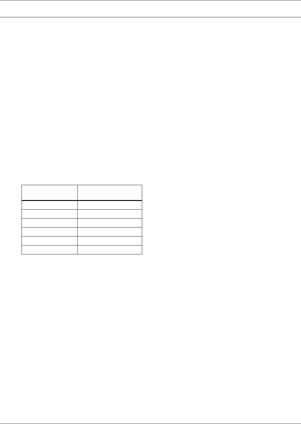
3.2 Heat Output
The unit produces minimal heat during normal operation.
3.3 Operating Environment
The unit is designed to be installed indoors where the ambient air temperature is in the range of 32°
and 104°F (0°C and 40°C) with a relative humidity of 0% to 95% non-condensing, up to an altitude of
4000 feet (1200 meters).
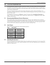
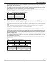
Table 1 Heat Output
Switch Size
Heat Output
BTU/Hr (kW)
100 amp 2,711 (0.80)
250 amp 4,680 (1.37)
400 amp 6,972 (2.04)
600 amp 10,520 (3.08)
800 amp 13,777 (4.03)
1000 amp 17,390 (5.09)