


Introduction to STS2 Operations
57
8.0 INTRODUCTION TO STS2 OPERATIONS
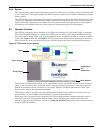
8.1 System Description
A STS2 provides an automatic, seamless transfer between input power sources to an output load. The
STS2 monitors the input sources, to ensure each source is operating within set parameters, as well as
ensure that each source is within acceptable tolerances for a transfer between sources to be com-
pleted.
The STS2 contains two static transfer switches in one enclosure to allow the unit to transfer its load
between the two input sources without disruption to the output for longer than 1/4 cycle.
If a problem is detected with a primary (Preferred) input source and defined trigger points are
reached, the STS2 automatically switches the input to the other (Alternate) input source. The STS2
continues to monitor both sources and can automatically transfer the load back to the preferred
source, if so configured, when that source returns to acceptable operating parameters.
The system control logic automatically monitors the input sources and power output to ensure that
they are operating within acceptable tolerances. The system logic manages the transfer between
sources.
The STS2 front panel contains either a Color Graphical Display on an LCD touch screen or an LED
display.
The Color Graphical Display provides a menu-driven operator interface, and a display of system infor-
mation, status information, a one-line diagram (Mimic) of the STS2, active alarms, and alarm history
information.
The menu selections provide control of the preferred source, manual transfer initiation. Buttons pro-
vide for audible alarm silence and reset.
Through the touch screen, specific voltage, current and environmental parameters can be configured
to trigger events that can sound an alarm, write to a history log and either transfer sources or inhibit
a transfer.
In units not equipped with the touch screen, LEDs provide the user with the ability to monitor the
STS2 and quickly assess problems.
Preferred input source selection, alarm reset and alarm silencing are done through buttons on the
touch screen, or push buttons with the LED display.
Communication options can be installed in the Color Graphical Display (LCD) unit only. These
options provide external communication with the STS2 through a modem, a network card, a program-
mable relay board, a contact isolator, or an RS-422 port to Liebert’s SiteScan.
8.1.1 Redundancy
Redundancy within the STS2 prevents one component from being a single point of failure, should a
problem occur. Redundant circuits and components are used to eliminate single points of failure.
Since the STS2 has two input sources, no single component failure can cause a loss of power to the
load. Redundant power supplies are provided which feed a DC dual-bus used throughout the unit to
prevent any single-point power supply failure modes.
Three separate redundant control logic modules are built into the system. Each contains the logic nec-
essary to run the STS2, and control all transfers.
Redundant fans are provided if a primary fan fails. The redundant fans turn on to prevent overheat-
ing inside of the unit.
Should the front panel interface fail, either touch screen or LEDs, the control logic continues to oper-
ate and the unit would transfer should a problem be detected on the preferred source. Information on
the monitoring parameters would be available through the remote communication options, if avail-
able, or the DB9 (RS-232) connector located next to the LCD display behind the front door. See
Figure 29 on page 41 for details.