


Specifications
113
15.2.4 Access
The STS2 is designed so all repairs and maintenance can be done from the front or top of the unit. All
components that may need repair or replacement during routine field maintenance are safely
accessed with the units in bypass without removing power from the unit. These components include:
• All electronic PCB assemblies
• Power supply assemblies
• All fuses
• All circuit breaker plug-in modules
•Fans
• SCRs
All power connections are designed to maintain proper connection torque over the lifetime of the unit
without any maintenance. The integrity of the connections can be checked via infrared scanning
safely from the front or top of the unit.
All other components including power cables and connections, circuit breaker bases, etc. are replace-
able from the front or top of the unit only, but this requires all power to be removed from the unit for
safety. Although routine re-torquing of the power connections is not required, if maintenance of these
connections is needed, complete removal of power is required from the unit for safety reasons.
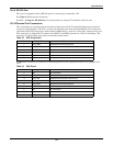
15.2.5 Circuit Breakers
The STS2 is equipped with five molded-case, plug-in, non-automatic circuit breakers. The breakers
are UL listed for use up to 600 VAC and CE marked. The plug-in feature of the breaker includes an
interlock, which prevents the breaker from being unplugged without being in the OFF (open) position.
Mechanical interlocks are provided on the breakers to prevent improper maintenance bypassing of
the solid-state switch. A bypass breaker cannot be closed unless the solid-state switch is connected to
the same input source and only one bypass breaker can be closed at a time. All breakers are equipped
with N.O. and N.C. auxiliary switches for monitoring of the breaker positions. The two input breakers
for the solid-state switching devices also are equipped with 48 VDC shunt trips to allow for control by
the STS2 logic. See the Circuit Breaker Schedule in Figure 20.
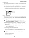
15.2.6 Cable Entrance
Removable conduit termination plates are provided in the top and bottom of the STS2 for termination
of the two source input conduits or raceways and/or the output conduits or raceways.
15.2.7 Doors
A removable key lock hinged front door provides access to the circuit breakers.
15.2.8 Color Graphical Display or LED Display
The display is located in the front of the unit. Front panel display is either an LCD touch screen dis-
play for monitoring and configuring the unit, or an LED panel to monitor the unit's status.
See Figure 31 for a drawing of the touch screen display. See Figure 63 for the layout of the LED dis-
play.
!
WARNING
Lethal voltages exist inside the unit during normal operation. Only qualified service
personnel should perform maintenance on the static switch.
The unit is supplied by more than one power source. The unit contains hazardous voltages if
any of the input sources is ON, even when the unit is in bypass. To isolate the unit, turn OFF
and lock out ALL input power sources.
Verify that all input power sources are de-energized and locked out before making connections
inside unit.