


Operating the LED Display STS2
104
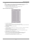
14.1.2 LED and push button description
The following table defines the LEDs and pushbuttons in the LED display:
Table 16 LED and push button description
Symbol LED Description Action
A Green Source 1 power is present
A green LED is lit if the Source 1 input power is present. This LED
only indicates that power is present to the power supply; it does not
indicate if the power is within the programmed tolerances of the unit.
B Green Source 2 power is present
A green LED is lit if the Source 2 input power is present. This LED
only indicates that power is present to the power supply; it does not
indicate if the power is within the programmed tolerances of the unit.
C Green Source 1 within tolerance
A green LED is lit if Source 1 power is within the programmed
tolerance for all phases.
D Green Source 2 within tolerance
A green LED is lit if Source 2 power is within the programmed
tolerance for all phases.
E Green Source 1 SCRs on A green LED is lit when the SCRs for Source 1 are closed.
F Green Source 2 SCRs on A green LED is lit when the SCRs for Source 2 are closed.
G Yellow Source transfer inhibited
A yellow (amber) LED is lit when source transfers are inhibited
(locked out) by a hardware condition. Connect a PC terminal to the
STS2 to locate the exact cause. See 12.0 - Communication
Interfaces for PC terminal commands.
H Green
Push button to select Source 1
as the preferred source
A green LED is lit if the button has been pushed to set Source 1 as
the preferred source.
I Green
Push button to select Source 2
as the preferred source
A green LED is lit if the button has been pushed to set Source 2 as
the preferred source.
J Green Output power is present
A green LED is lit to indicate that power is present on the output
load.
K Alarm silence button
Push this button to turn off the horn that is sounded for an alarm.
This button does not reset an alarm condition, unless pushed
simultaneously with “M” button.
L
Symbol to indicate the K and M
must be pushed at the same
time to reset alarm
M Alarm reset push button
Push this button simultaneously with the “K” button to reset an alarm
condition. An alarm can only be reset if the hardware condition
permits a reset.
N Red Alarm present
A red LED is lit when an alarm condition is present in the STS2.
Connect a PC terminal to the STS2 to locate the exact cause. See
12.0 - Communication Interfaces for PC terminal commands.
1 Green CB1 closed
A green LED is lit if CB1 is closed, indicating power is flowing to the
static transfer switch from Source 1.
2 Green CB2 closed
A green LED is lit if CB2 is closed, indicating power is flowing to the
static transfer switch from Source 2.
3 Green CB3 closed A green LED is lit if the output breaker/switch is closed.
3A Green CB3A closed
A green LED is lit if the output breaker/switch is closed. CB3A is
installed on units with dual output breakers.
4 Yellow CB4 closed A yellow LED is lit if the Source 1 bypass breaker/switch is closed.
5 Yellow CB5 closed A yellow LED is lit if the Source 2 bypass breaker/switch is closed.