


v
FIGURES
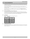
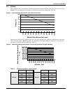
Figure 1 Recommended derating for high altitude operation . . . . . . . . . . . . . . . . . . . . . . . . . . . . . . . . . . . . . 7
Figure 2 Maximum ambient temperature for full load operation at higher altitudes. . . . . . . . . . . . . . . . . . 7
Figure 3 Typical static transfer switch one-line diagram . . . . . . . . . . . . . . . . . . . . . . . . . . . . . . . . . . . . . . . . 9
Figure 4 Typical one-line diagram of two PDUs and a static transfer switch . . . . . . . . . . . . . . . . . . . . . . . 11
Figure 5 Outline drawing: 100 – 250 amp STS2 . . . . . . . . . . . . . . . . . . . . . . . . . . . . . . . . . . . . . . . . . . . . . . 17
Figure 6 Outline drawing: 400 – 600 amp STS2 . . . . . . . . . . . . . . . . . . . . . . . . . . . . . . . . . . . . . . . . . . . . . . 18
Figure 7 Outline drawing: 800 – 1000 amp STS2 . . . . . . . . . . . . . . . . . . . . . . . . . . . . . . . . . . . . . . . . . . . . . 19
Figure 8 Outline drawing: 100 – 250amp STS2 with a key lockout switch option . . . . . . . . . . . . . . . . . . . 20
Figure 9 Outline drawing: 400 – 600 amp STS2 with a key lockout switch option . . . . . . . . . . . . . . . . . . . 21
Figure 10 Outline drawing: 800 – 1000 amp STS2 with the key lockout switch option . . . . . . . . . . . . . . . . 22
Figure 11 Seismic anchor drawing: 100 – 250 amp STS2 . . . . . . . . . . . . . . . . . . . . . . . . . . . . . . . . . . . . . . . . 23
Figure 12 Seismic anchor drawing: 400 – 600 amp STS2 . . . . . . . . . . . . . . . . . . . . . . . . . . . . . . . . . . . . . . . . 24
Figure 13 Seismic anchor drawing: 800 – 1000 amp STS2 . . . . . . . . . . . . . . . . . . . . . . . . . . . . . . . . . . . . . . . 25
Figure 14 Electrical field connections drawing: 100 – 250 amp STS2 with single output breaker. . . . . . . . 26
Figure 15 Electrical field connections drawing: 100 – 250 amp STS2 with dual output breakers . . . . . . . . 27
Figure 16 Electrical field connections drawing: 400 – 600 amp STS2 with single output breaker. . . . . . . . 28
Figure 17 Electrical field connections drawing: 400 – 600 amp STS2 with dual output breakers . . . . . . . . 29
Figure 18 Electrical field connections drawing: 800 – 1000 amp STS2 with single output breaker. . . . . . . 30
Figure 19 Electrical field connections: 800 – 1000 amp STS2 with dual output breakers . . . . . . . . . . . . . . 31
Figure 20 Circuit breaker schedule. . . . . . . . . . . . . . . . . . . . . . . . . . . . . . . . . . . . . . . . . . . . . . . . . . . . . . . . . . 32
Figure 21 Control connection location diagram: 100 – 600 amp STS2 . . . . . . . . . . . . . . . . . . . . . . . . . . . . . . 33
Figure 22 Control connection location diagram: 800 – 1000 amp STS2 . . . . . . . . . . . . . . . . . . . . . . . . . . . . . 34
Figure 23 Control wiring for remote source selection option. . . . . . . . . . . . . . . . . . . . . . . . . . . . . . . . . . . . . . 35
Figure 24 Control wiring for the programmable relay board option. . . . . . . . . . . . . . . . . . . . . . . . . . . . . . . . 36
Figure 25 Control wiring for the input contact isolator board option . . . . . . . . . . . . . . . . . . . . . . . . . . . . . . . 37
Figure 26 Control wiring for comms board (see Figure 27 on page 39 for internal modem wiring) . . . . . . 38
Figure 27 Control wiring for the internal modem option . . . . . . . . . . . . . . . . . . . . . . . . . . . . . . . . . . . . . . . . 39
Figure 28 Control wiring for the network interface card (NIC) option. . . . . . . . . . . . . . . . . . . . . . . . . . . . . . 40
Figure 29 Control wiring for the RS-232 port . . . . . . . . . . . . . . . . . . . . . . . . . . . . . . . . . . . . . . . . . . . . . . . . . 41
Figure 30 Outline drawing for input junction box . . . . . . . . . . . . . . . . . . . . . . . . . . . . . . . . . . . . . . . . . . . . . . 42
Figure 31 Color LCD touch screen display . . . . . . . . . . . . . . . . . . . . . . . . . . . . . . . . . . . . . . . . . . . . . . . . . . . . 43
Figure 32 LED display. . . . . . . . . . . . . . . . . . . . . . . . . . . . . . . . . . . . . . . . . . . . . . . . . . . . . . . . . . . . . . . . . . . . 44
Figure 33 Installation drawing, seismic floor stand 100-250A . . . . . . . . . . . . . . . . . . . . . . . . . . . . . . . . . . . . 45
Figure 34 Installation drawing, seismic floor stand 100-250A . . . . . . . . . . . . . . . . . . . . . . . . . . . . . . . . . . . . 46
Figure 35 Installation drawing, seismic floor stand 100-250A . . . . . . . . . . . . . . . . . . . . . . . . . . . . . . . . . . . . 47
Figure 36 Installation drawing, seismic floor stand 100-250A . . . . . . . . . . . . . . . . . . . . . . . . . . . . . . . . . . . . 48
Figure 37 Installation drawing, seismic floor stand 400-600A . . . . . . . . . . . . . . . . . . . . . . . . . . . . . . . . . . . . 49
Figure 38 Installation drawing, seismic floor stand 400-600A . . . . . . . . . . . . . . . . . . . . . . . . . . . . . . . . . . . . 50
Figure 39 Installation drawing, seismic floor stand 400-600A . . . . . . . . . . . . . . . . . . . . . . . . . . . . . . . . . . . . 51
Figure 40 Installation drawing, seismic floor stand 400-600A . . . . . . . . . . . . . . . . . . . . . . . . . . . . . . . . . . . . 52
Figure 41 Installation drawing, seismic floor stand 800-1000A . . . . . . . . . . . . . . . . . . . . . . . . . . . . . . . . . . . 53
Figure 42 Installation drawing, seismic floor stand 800-1000A . . . . . . . . . . . . . . . . . . . . . . . . . . . . . . . . . . . 54
Figure 43 Installation drawing, seismic floor stand 800-1000A . . . . . . . . . . . . . . . . . . . . . . . . . . . . . . . . . . . 55
Figure 44 Installation drawing, seismic floor stand 800-1000A . . . . . . . . . . . . . . . . . . . . . . . . . . . . . . . . . . . 56
Figure 45 STS2 touch screen display . . . . . . . . . . . . . . . . . . . . . . . . . . . . . . . . . . . . . . . . . . . . . . . . . . . . . . . . 59
Figure 46 STS2 touch screen display . . . . . . . . . . . . . . . . . . . . . . . . . . . . . . . . . . . . . . . . . . . . . . . . . . . . . . . . 65
Figure 47 Source transfer screen . . . . . . . . . . . . . . . . . . . . . . . . . . . . . . . . . . . . . . . . . . . . . . . . . . . . . . . . . . . 66
Figure 48 Gate board viewing slot locations. . . . . . . . . . . . . . . . . . . . . . . . . . . . . . . . . . . . . . . . . . . . . . . . . . . 68
Figure 49 STS2 touch screen display . . . . . . . . . . . . . . . . . . . . . . . . . . . . . . . . . . . . . . . . . . . . . . . . . . . . . . . . 85
Figure 50 Menus . . . . . . . . . . . . . . . . . . . . . . . . . . . . . . . . . . . . . . . . . . . . . . . . . . . . . . . . . . . . . . . . . . . . . . . . 86
Figure 51 Keyboard and keypad displays. . . . . . . . . . . . . . . . . . . . . . . . . . . . . . . . . . . . . . . . . . . . . . . . . . . . . 86
Figure 52 Key lockout switch. . . . . . . . . . . . . . . . . . . . . . . . . . . . . . . . . . . . . . . . . . . . . . . . . . . . . . . . . . . . . . . 87