


α
2 Simple Application Controllers
The Command String 7
7 - 18
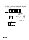
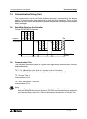
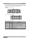
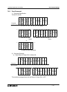
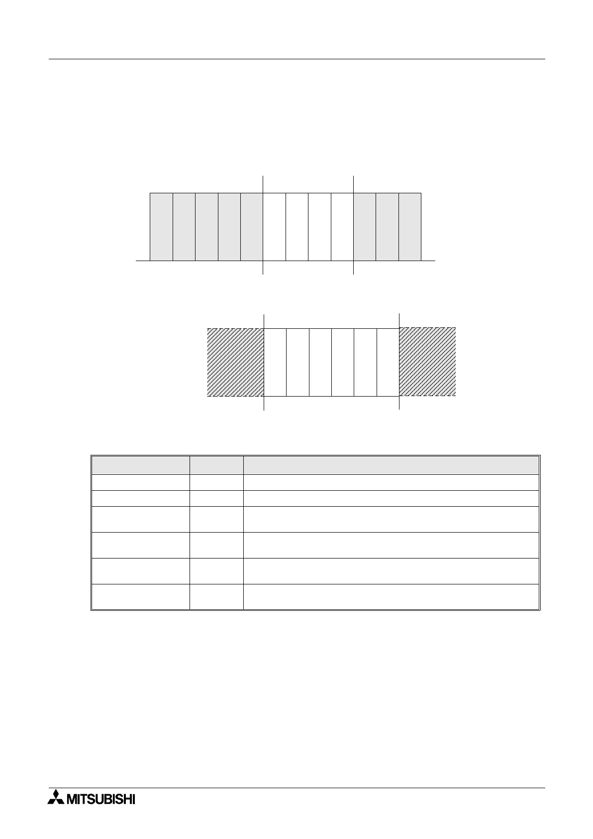
The following illustration demonstrates the format structure for writing word data. Writing word
data requires the Device Status to contain a lower and higher byte, therefore, the data
transmission area is extended by one byte when writing to WORD data
WORD Data
Format B - WRITE Message - WORD data
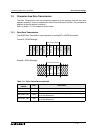
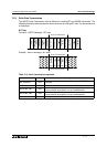
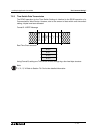
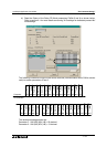
Example - WRITE Message - WORD data
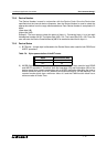
Table 7.13: Data Transmission explained
Control element Hex Description
No. of devices 01H There is only one intended device to be READ from the controller
Device Code 69H The device is from the Communication Word Range.
Device No. (LB) 04H
The lower byte in conjunction with the higher byte indicates
Communication Word device 4 is the intended device.
Device No. (HB) 00H
The higher byte in conjunction with the lower byte indicates
Communication Word device 4 is the intended device.
Device Status (LB) 2BH
The lower byte in conjunction with the higher byte indicates a
value of 4651 decimal
Device Status (HB) 12H
The higher byte in conjunction with the lower byte indicates a
value of 4651 decimal
S
T
X
E
T
X
No. comm
bytes
Format No.
Station
No.
Command
No. of devices
Device code
Device No.
(LB)
Device No.
(HB)
Sum check
(LB)
Sum check
(HB)
Data Transmission
Data Transmission
Data Transmission
Data Transmission
No. of
devices
01H
Device No.
(LB)
04H
Device
code
69H
Device No.
(HB)
00H
Device
Status
Device
Status
2BH
12H