α
2 Simple Application Controllers
Computer Link - Dedicated Protocol 5
5 - 3
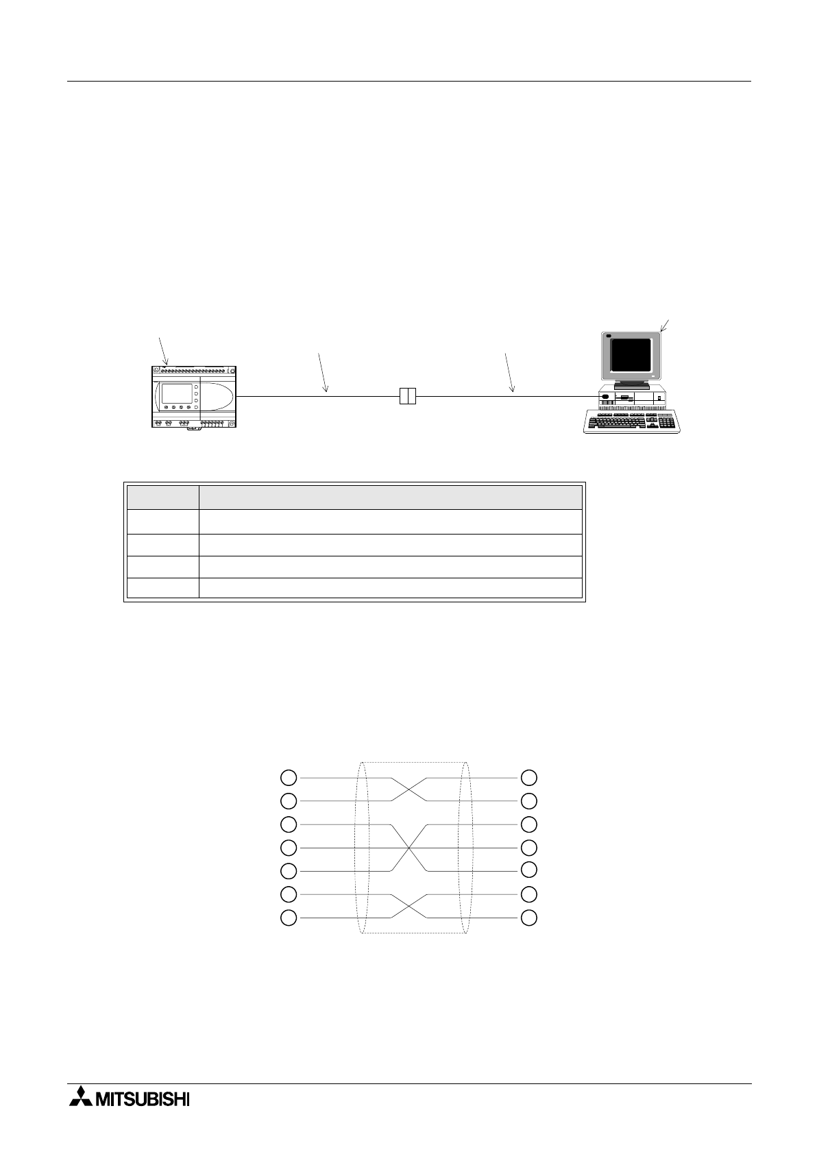
5.2 Configuration Diagram
The Peripheral equipment acts as the Master in all configurations, hence, messages are never
initiated from the
α
2 Series Controller. This configuration involves a personal computer acting
as the Master and the
α
2 Series Controller the slave unit.
Currently the
α
2 Series Controller contains an RS-232C interface, thus, only 1:1
communication is available.
5.2.1 Cross-Cable Diagram
The pinouts and connector types for the RS-232C cross cable are shown in the figure below.
Both the connectors and the wiring are equivalent so that either side can be connected to the
AL2-GSM-CAB or the peripheral device.
Note:
The 4 and 7 signals must be set to high-level on the personal computer side. If these signals
are not set, the personal computer will to communicate with the
α
2 Series Controller.
Table 5.1: Configuration Table
No. Description
1
α
2 Series Co
ntroller
2 AL2-GSM-CAB
3 RS-232C Cross Cable
4 PC or other peripheral equipment
OUT1
OK
-
+
ESC
OUT3
9
RELAY
OUTPUT
6 5
OUT
8
OUT2 OUT4
7
DC INPUT
15 14 13 12 11 10 9 8 7 6 5 4 3 2 1
(B) (A)
+ -
24V DC
POWER
AL2-24MR-D
f
c
d e
(9-pin D-Sub female) (9-pin D-Sub female)
2
3
8
7
6
5
4
3
2
7
8
4
5
6


