α
2
Simple Application Controllers
SMS/SMR/CD Functions and the Modem Setting 2
2 - 6
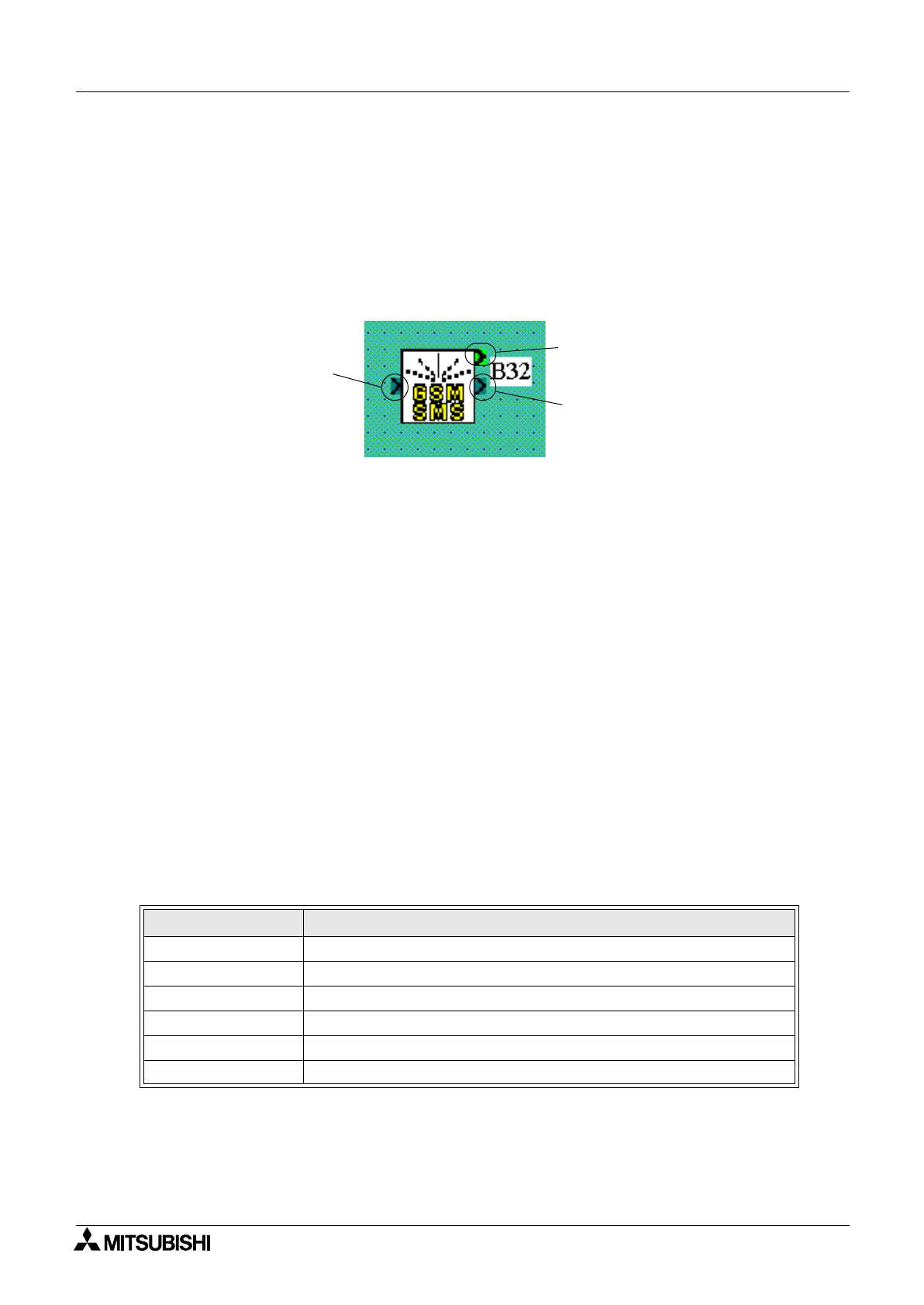
2.2 The GSM/SMS Function Block
The GSM/SMS Function block is the trigger to send SMS messages. To enter or edit the GSM/
SMS parameters, double click on the icon to open the Short Message Service dialog box
described in Section 2.2.2.
When two or more Function Blocks are trying to send a message at the same time, the first to
connect will send its SMS message. The other GSM/SMS FB(s) will be placed in “Wait” status.
All the FBs will send their messages in turn.
A) The Input Signal
The
α
2 controller will send the SMS message to the chosen destination when the input pin is
activated. Even if the Input pin is turned OFF during the process, the operation will continue
until the message is sent or three retries have been completed.
Input signals will be ignored when the Output pin is On or the when the Function Block is in
“Wait” status.
B) The Output Signal
The Output signal comes ON when the SMS message has been successfully sent or the final
retry has taken place.
If the Input signal that began the operation remains ON, the Output will remain ON.
If the Input signal turns OFF during the send operation, the Output signal will remain ON for
one program scan after the send operation is complete and then turn OFF.
C) The Word Output
Check the status of the transmission by checking the Output Word data. The data can be
checked in the program or by connecting the Output Word data to a Display FB.
Table 2.3: Output Word Value
Bit Description
b0 Transmission is Complete
b1 Transmission or retry in Progress
b2 Transmission is in “Wait” status
b3 Transmission Failed
b4 Transmission did not occur due to an SMS Parameter Error
b5 - b15 Reserved, will always be 0
A)
(B
(C


