α
2 Simple Application Controllers
The Command String 7
7 - 5
7.3 Control Protocol elements
The following section will explain the control elements used in the
α
2 Series Dedicated
protocol Transmit/Receive message. Refer to section 7.6 for detailed information concerning
the commands available with this protocol.
The
α
2 Series Controller is not a ASCII generated format, but comprised of a 8-bit binary
structure.
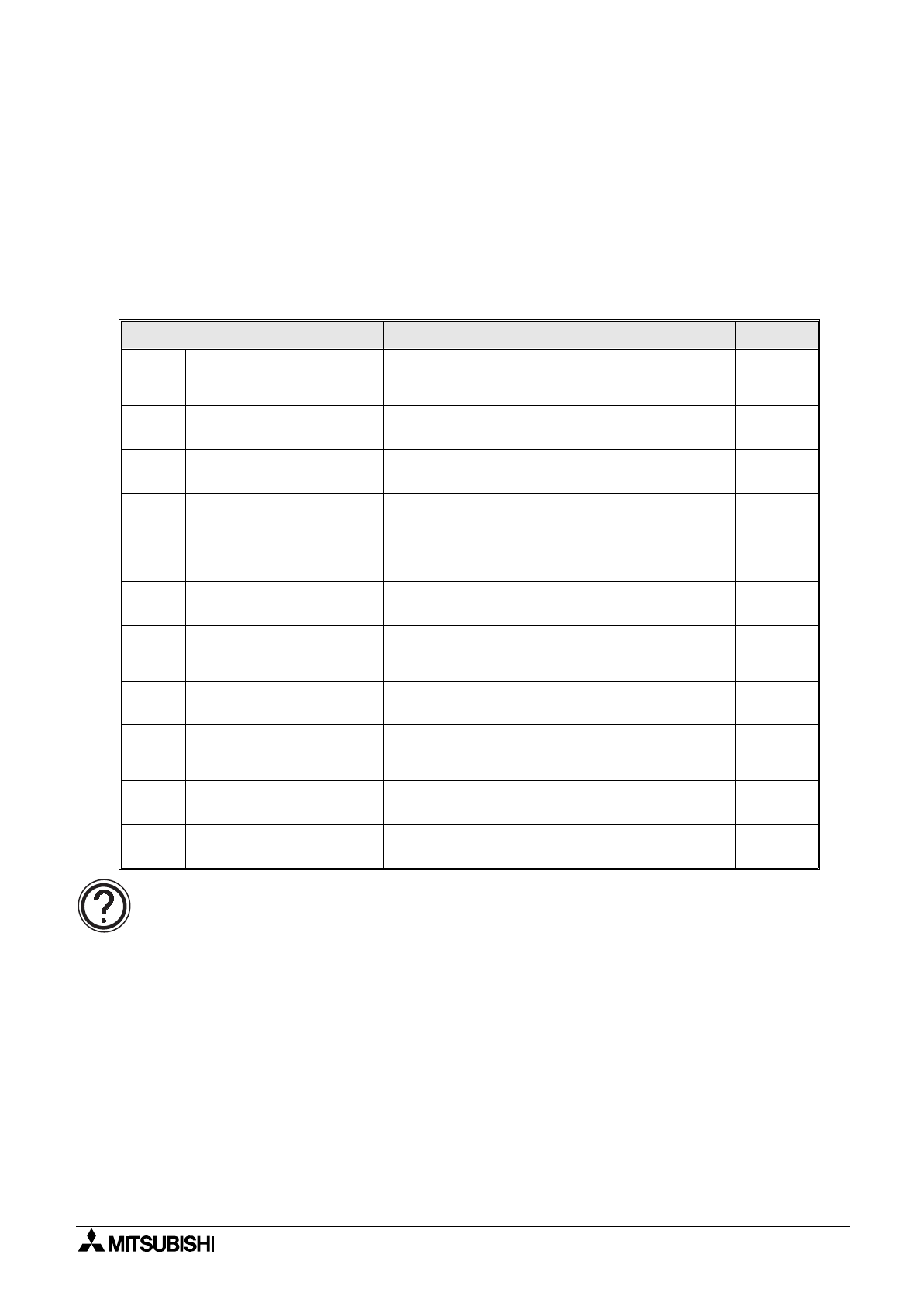
Table 7.3: Format A and B protocol elements
Control Element Description Section
1) Control Codes
The Control codes are one byte hexadecimal
ASCII representation of standard protocol
terminology.
7.3.1
2) No. Communication Bytes
Standard number of bytes in one transmit/
receive message.
7.3.2
3) Format No.
Format number used to identify Format A or
Format B type protocol message.
7.3.3
4) Station No.
Assigned station number for controller
identification.
7.3.4
5) Command
Read, Write or Remote RUN/STOP operation
are declared as the commands.
7.3.5
6) No. of Devices
Total number of internal devices or I/O that are to
be read/written from/to the controller.
7.3.6
7) Device Code
Each individual internal device has been given a
device code. The single byte code cannot be
changed from original default setting.
7.3.7
8) Device No.
Head address of the internal device or I/O being
read or written from/to the controller.
7.3.8
9) Device Status
Available only to Transmit message in write
mode for Format B and reply sent from the
controller when in Read mode for Format B.
7.3.9
10) Sum Check
Sum check used to verify that the data in a
message has not been corrupted.
7.3.10
11) Error Code
Specific error coded relating to either sum check,
protocol, device or remote error.
7.3.11


