


Chapter 3 Handling Plates
Chapter 3 Handling plates
3.1 Plate setting
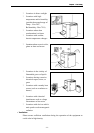
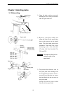
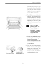
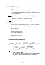
1) Open the plate setting cover and,
holding the lever with your thumb,
take the spool shaft out.
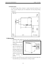
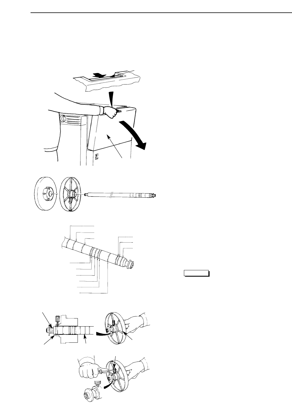
2) Refer to your plate width, and
align the edge of the spool plate
boss to the groove in the spool
shaft. The spool shaft grooves are
numbered from outer side in the
following order: 414, 404, 400,
370, 340, 335, 324, 310, 305, 279,
254, and 229.
Red tape is affixed to the
reference side of the
spool shaft.
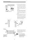
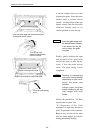
3) To prevent the reference side of
the spool plate from shifting from
its designated position, insert a
screw driver into the set screw
hole and firmly fix the set screw to
the spool shaft.
Always fix the set screw on the
flat side of the spool shaft.
Caution
- 19 -
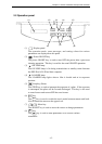
Lever
Plate setting cover
229 (9)
254 (10)
279 (11)
305 (12)
310 (12 1/5)
Marker
Spool plate
Set screw
Red tape
Spool shaft
Edge of boss
400 (15 3/4)
324 (12 3/4)
335 (13 3/16)
340 (13 3/8)
370 (14 9/16)
404 (15 7/8)
414 (16 3/10)