1-3LAYOUT & INSTALLATION
1
2
3
4
5
6
7
8
9
10
11
12
13
14
A
LAYOUT & INSTALLATION
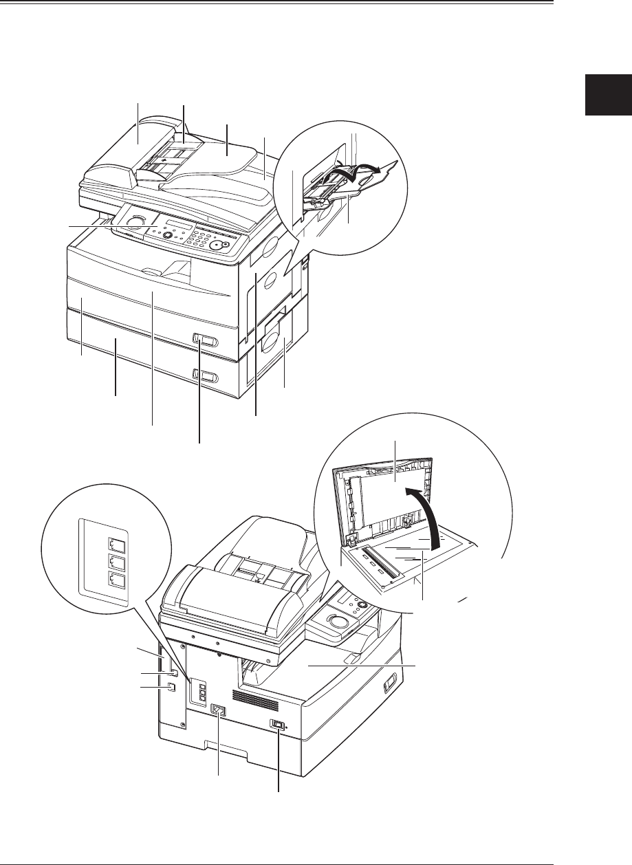
Machine layout
The following illustration uses the MFX-1330. All illustrations used in this manual are of the MFX-
1330 unless otherwise noted.
L
IN
E
P
H
O
N
E
1
P
H
O
N
E
2
LIN
E
PHONE1
PHONE2
Bypass tray
Automatic
document feeder
(ADF)
Control panel
Paper cassette
2nd paper cassette
(Option)
1st side cover
2nd side cover
Front cover
Paper level
Indicator
Document
guides
Document
tray
Document
exit tray
Document glass
Power switch
AC power jack
Telephone
Connector
s
Platen cover
Paper exit tray
Second phone line
(Option)
Network connector
(Option)
USB connector
The document glass
is available only fo
r
the MFX-1330.


