


Chapter 1 Introduction
© National Instruments Corporation 1-3 DIO 6533 User Manual
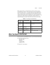
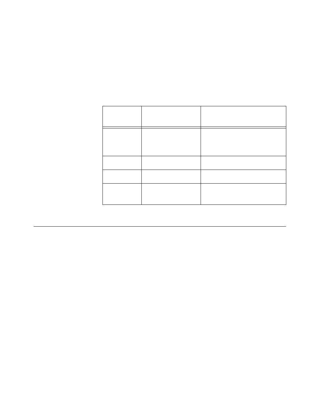
PXI specific features are implemented on the J2 connector of the
CompactPCI bus. Table 1-1 lists the J2 pins used by your PXI-6533
device. Your PXI device is compatible with any CompactPCI chassis
with a sub-bus that does not drive these lines. Even if the sub-bus is
capable of driving these lines, the PXI device is still compatible as long
as those pins on the sub-bus are disabled by default and not ever
enabled. Damage may result if these lines are driven by the sub-bus.
What You Need to Get Started
To set up and use your DIO 6533 device, you will need the following:
❑ One of the following devices:
PCI-DIO-32HS
PXI-6533
AT-DIO-32HS
DAQCard-6533
❑ DIO 6533 User Manual
Table 1-1.
Pins Used by the PXI-6533 Device
PXI-6533
Signal
PXI Pin Name PXI J2 Pin Number
RTSI
Trigger
(0..6)
PXI Trigger (0..6) B16, A16, A17, A18, B18,
C18, E18
Reserved PXI Star D17
RTSI Clock PXI Trigger (7) E16
Reserved LBR (7, 8, 10, 11,
12)
A3, C3, E3, A2, B2