


Chapter 2 Installation and Configuration
DIO 6533 User Manual 2-6 © National Instruments Corporation
Base I/O Address Selection
The AT-DIO-32HS device can be configured to use a base address in
the range of 100 to 3E0 hex. The AT-DIO-32HS occupies 16 bytes of
address space and must be located on a 16-byte boundary. Therefore,
valid addresses include 100, 110, 120, ..., 3D0, 3E0 hex. This selection
is software configured and does not require you to manually change any
settings on the device.
DMA Channel Selection
The AT-DIO-32HS can achieve high transfer rates by using up to two
16-bit DMA channels. The AT-DIO-32HS can use only 16-bit DMA
channels, which correspond to channels 5, 6, and 7 in an AT (16-bit
ISA) computer and channels 0, 1, 2, 3, 5, 6, and 7 in an EISA computer.
These selections are all software configured and do not require you to
manually change any settings on the device.
Interrupt Channel Selection
The AT-DIO-32HS increases bus efficiency by using an interrupt
channel for event notification. The AT-DIO-32HS can use interrupt
channel 3, 4, 5, 6, 7, 9, 10, 11, 12, 14, or 15. This selection is software-
configured and does not require you to manually change any settings on
the device.
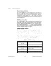
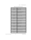
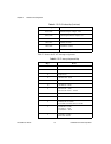
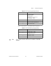
Tables 2-1, 2-2, and 2-3 provide information concerning possible
conflicts in base address, DMA channel, and interrupt channel
assignment when configuring your AT-DIO-32HS device.
Table 2-1.
PC AT I/O Address Map
I/O Address Range (Hex) Device
100 to 1EF —
1F0 to 1F8 IBM PC AT Fixed Disk
200 to 20F PC and PC AT Game Controller, reserved
210 to 213 PC-DIO-24 – default
218 to 21F —
220 to 23F Previous generation of AT-MIO boards – default