


© National Instruments Corporation 4-1 DIO 6533 User Manual
Chapter
4
Signal Connections
This chapter describes how to make input and output signal connections
to your DIO6533 device via the device I/O connector and RTSI
connector.
The I/O connector for the 6533 device has 68 pins. You can connect the
6533device to 68-pin accessories through an SH68-68-D1 shielded
cable or an R6868 ribbon cable. Using an optional 68-to-50 pin
6533device adapter, you can also connect your 6533device to 50-pin
accessories through an NB1ribbon cable.
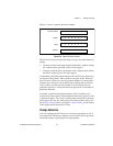
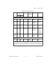
I/O Connector
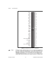
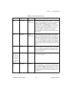
Figure4-1 shows the pin assignments for the 68-pin 6533 device I/O
connector. Refer to AppendixB, Optional Adapter Description, for the
pin assignments for the 68-to-50 pin adapter.
Caution:
Connections that exceed any of the maximum input or output ratings
onthe 6533
may damage your device and your computer. See AppendixA,
Specifications
, for maximum ratings. This warning includes connecting
any power signals to ground and vice versa. National Instruments is
NOT
liable for any damages resulting from any such signalconnections.
!