


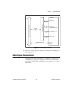

Chapter 4 Signal Connections
© National Instruments Corporation 4-13 DIO 6533 User Manual
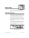
Strobed applications include digital data acquisition, digital waveform
generation, and data transmission to or from an external device.
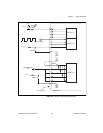
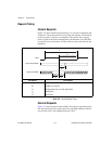
Timing Connections
Timing connections include the REQ, ACK (STARTTRIG), and
STOPTRIG pins for pattern generation, and the REQ, ACK, and PCLK
pins for two-way handshaking operation.
The 6533 device provides two handshaking groups, each with its own
timing connections. To perform pattern generation or handshaking, you
must first associate a set of data pins with a group. Do this by assigning
data ports to handshaking groups.
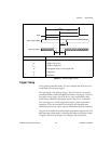
Chapter5, Signal Timing, details the connection and timing of each
pattern generation and handshaking control signal.
Pull-Up and Pull-Down Connections
The CPULL and DPULL lines enable you to select the biasing of the
control and data signals.
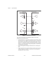
If you drive the CPULL pin low, connect the CPULL pin to a GND pin,
or leave the CPULL line disconnected, the 6533 device pulls all its
control lines down to 0V with 2.2kΩ resistors. If you drive the CPULL
pin high or connect the CPULL pin to the +5V pin, the 6533device
pulls all its control lines to +5V with the same 2.2kΩ resistors.
Similarly, if you drive the DPULL pin low, connect the DPULL pin to
a GND pin, or leave the DPULL line disconnected, the 6533 device
pulls all its data lines down to 0V with 100kΩ resistors. If you drive
the DPULL pin high or connect the DPULL pin to the +5V pin, the
6533 device pulls all its control lines to +5V with the same 100kΩ
resistors.
Do not connect CPULL, DPULL, or any other line directly to an
external power supply while the 6533 device is powered off.
The 6533 device drivers power up and reset to high-impedance states.
Therefore, the CPULL and DPULL lines control whether you get high
or low control and data lines, respectively, when you power up the 6533
device or reset its drivers.