


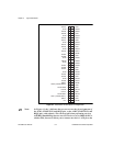

Chapter 4 Signal Connections
DIO 6533 User Manual 4-6 © National Instruments Corporation
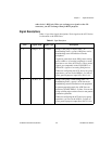
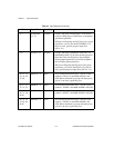
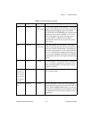
Signal Characteristics
Following is a list of signal characteristics. Characteristics are for all
signals, unless otherwise noted. For signal characteristics not given in
this section, see AppendixA, Specifications.
• Drive current—After being enabled, all lines that can be configured
for output sink at least 24mA at 0.4V, and source at least 24mA
at 2.4V.
♦ DAQCard-6533—Your PCMCIA socket may not provide
sufficient power to drive all outputs at 24mA.
• Ground reference—All signals are referenced to the GND lines.
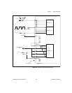
• Initial state—At power up, all control and data lines begin at high
impedance. With no load attached, the voltage levels of the lines
are controlled by the pull-up or pull-down resistors.
• Pull-up/pull-down
• Control lines—All timing control lines have 2.2kΩ pull-up or
pull-down resistors, controlled by the CPULL line.
• Data lines—All timing data lines have 100kΩ pull-up or
pull-down resistors, controlled by the DPULL line.
• Bias-selection lines—The CPULL and DPULL lines, which
select the bias of the control and data lines, are themselves
biased low with 20kΩ pull-down resistors. The default bias of
all lines, therefore, is pulled down.
• Polarity
• Data signals—Active high. A 1 corresponds to a high voltage,
and a 0 corresponds to a low voltage.
• Control signals—Depending on the operating mode and
handshaking protocol you select, control signals can be active
high or active low.