


Chapter 4 Signal Connections
© National Instruments Corporation 4-3 DIO 6533 User Manual
other device’s REQ pin. When you exchange two signals on the I/O
connector, you also exchange them for RTSI purposes.
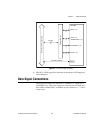
Signal Descriptions
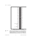
Table 4-1 provides signal descriptions. Each signal on the 6533 device
is referenced to the GND lines.
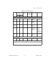
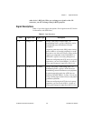
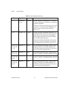
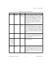
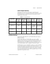
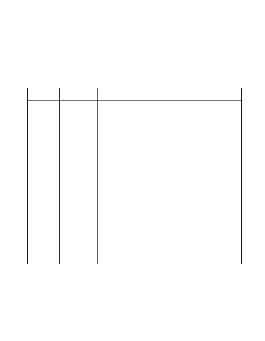
Table 4-1.
Signal Descriptions
Pins Signal Name Signal Type Description
2, 9 REQ<1..2> Control Group 1 and group 2 request lines—In
handshaking mode, a group’s REQ line carries
handshaking status information from the
peripheral.
In pattern generation mode, REQ carries timing
pulses either to or from the peripheral to strobe
data into or out of the 6533 device. These strobe
signals are comparable to the CONVERT* or
UPDATE* signals of an analog DAQ device.
When not configuring the 6533 device for group
operations, you can use the REQ<1..2> lines as
extra, general-purpose input lines (IN<3..4>).
3, 8 ACK<1..2> Control Group 1 and group 2 acknowledge lines—In
handshaking mode, a group’s ACK line carries
handshaking control information to the peripheral.
In pattern generation mode, the ACK lines can
function as STARTTRIG<1..2> lines. You can use
rising or falling edges on these lines to start pattern
generation operations.
When not configuring the 6533 device for group
operations, you can use the ACK<1..2> lines as
extra, general-purpose output lines (OUT<3..4>).