


Chapter 4 Signal Connections
DIO 6533 User Manual 4-8 © National Instruments Corporation
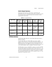
Board and RTSI Clocks
The 6533 device requires a frequency timebase to run the handshaking
logic and to generate intervals for pattern generation. The frequency
timebase must be 20MHz.
Either the 6533 device can use its internal 20MHz clock source as the
timebase, or you can provide a timebase from another 20MHz device
over the RTSI bus. When using its internal 20MHz timebase, the
6533device can also drive its internal timebase onto the bus and to
another device that uses a 20MHz clock.
The 20MHz timebase, whether local or imported from the RTSI bus,
serves as the primary frequency source for the 6533 device. You can
select a clocking configuration through software. By default, the
6533device uses its own internal timebase, without driving the RTSI
bus clock line.
♦ PXI-6533—The PXI-6533 uses PXI trigger line7 as its RTSI clock line.
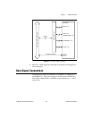
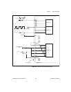
RTSI Triggers
The seven trigger lines on the RTSI bus provide a very flexible
interconnection scheme for any device sharing the RTSI or trigger bus.
Any 6533 device control signal can connect to a RTSI or trigger bus
line. You can drive output control signals onto the bus and receive input
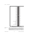
control signals from the bus. Figure4-2 shows the signal connection
scheme.