


Chapter 2 Installation and Configuration
DIO 6533 User Manual 2-8 © National Instruments Corporation
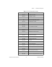
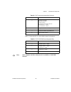
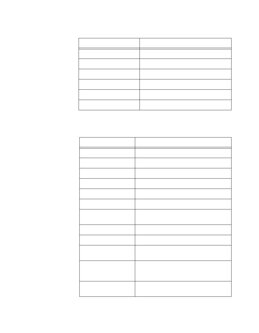
Table 2-2 shows the PC AT interrupt assignments.
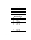
3C0 to 3CF Enhanced Graphics Adapter, VGA
3D0 to 3DF Color/Graphics Monitor Adapter, VGA
3E0 to 3EF —
3F0 to 3F7 Diskette Controller
3F8 to 3FF Serial Port 1 (COM1)
A79 Reserved for Plug and Play operation
Table 2-2. PC AT Interrupt Assignment Map
IRQ Device
15 Available
14 Fixed Disk Controller
13 Coprocessor
12 AT-DIO-32F – default
11 AT-DIO-32F – default
10 AT-MIO-16 – default
9 PC Network – default
PC Network Alternate – default
8 Real-Time Clock
7 Parallel Port 1 (LPT1)
6 Diskette Drive Controller
Fixed Disk and Diskette Drive Controller
5 Parallel Port 2 (LPT2)
PC-DIO-24 – default
Lab-PC/PC+ – default
4 Serial Port 1 (COM1)
BSC, BSC Alternate
Table 2-1. PC AT I/O Address Map (Continued)
I/O Address Range (Hex) Device