


Chapter 4 Signal Connections
DIO 6533 User Manual 4-14 © National Instruments Corporation
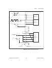
You should connect DPULL to +5V when using any wired-OR output
drivers. In other cases, you can use the CPULL and DPULL lines to
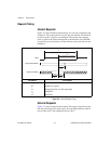
select a power-up state that is inactive in your application. For example,
if you are using active-low handshaking signals, you can connect the
CPULL line to +5V to place the handshaking lines in the high, inactive
state at power up.
Power Connections
The +5V pin on the I/O connector supplies power from the computer
power supply through a self-resetting fuse. The fuse resets
automatically within a few seconds after removal of an overcurrent
condition. The power pin is referenced to the GND pins and can supply
power to external, digital circuitry.
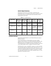
♦ PCI-DIO-32HS, PXI-6533, and AT-DIO-32HS:
• Power rating: +4.65 to +5.25VDC at 1A
♦ DAQCard-6533:
• Power rating: +4.65 to 5.25VDC at 250mA
You can connect the +5V pin to the CPULL and DPULL pins to control
the bias of the 6533 device control and data pins, as described in the
Pull-Up and Pull-Down Connections section in this chapter.
Caution: Do not connect the +5V power pin directly to the GND, RGND, or any
output pin of the 6533 device or any voltage source or output pin on
another device. Doing so can damage the device and the computer.
National Instruments is
NOT
liable for damages resulting from such a
connection.
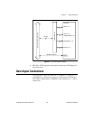
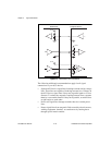
Field Wiring and Termination
Transmission line effects and environmental noise, particularly on
clock and control lines, can lead to incorrect data transfers if you do not
take proper care when running signal wires to and from the device.
Note: Make sure your 6533 device and your peripheral device share a common
ground reference. Connect one or more 6533 device GND lines to the
ground reference of your peripheral device.
!