


Chapter 4 Signal Connections
© National Instruments Corporation 4-7 DIO 6533 User Manual
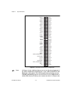
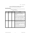
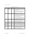
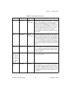
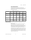
Control Signal Summary
The direction and function of each group’s signal timing and
handshaking lines vary, depending on the mode of operation you select
for the group. Table4-2 shows the direction and function of each
control signal in each mode.
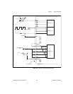
RTSI Bus Interface
The PCI-DIO-32HS, PXI-6533, and AT-DIO-32HS each contains a
RTSI bus interface.
The PCI-DIO-32HS and AT-DIO-32HS each contains a RTSI
connector and an interface to the National Instruments RTSI bus. The
RTSI bus provides seven trigger lines and a system clock line. All
National Instruments AT and PCI boards that have RTSI bus connectors
can be cabled together inside a computer to share these signals.
The PXI-6533 uses pins on the PXI J2 connector to connect the RTSI
bus to the PXI trigger bus as defined in the PXI Specification, rev. 1.0.
All National Instruments PXI boards that provide a connection to these
pins can be connected together by software. This feature is available
only when the PXI-6533 is used in a PXI-compatible chassis. It is not
supported in CompactPCI chassis.
Table 4-2.
Control Signal Summary
Signal Name Direction in
Handshaking
Mode
Function in
Handshaking
Mode
Direction in
Pattern
Generation
Function in
Pattern
Generation
Function in
Unstrobed
Mode
REQ<1..2> input request input or
output
request extra inputs
(IN<3..4>)
ACK<1..2> output acknowledge input start trigger
(START–
TRIG<1..2>)
extra outputs
(OUT<3..4>)
STOPTRIG<1..2> — — input stop trigger extra inputs
(IN<1..2>)
PCLK<1..2> input or output peripheral
clock
— — extra outputs
(OUT<1..2>)