Chapter 4 Signal Connections
© National Instruments Corporation 4-15 DIO 6533 User Manual
Take the following precautions to ensure a uniform transmission line
and minimize noise pickup:
• Use twisted-pair wires to connect digital I/O signals to the device.
Twist each digital I/O signal with a GND line.
• Place a shield around the wires connecting digital I/O signals to the
device.
• Route signals to the device carefully. Keep cabling away from
noise sources. The most common noise source in a PC-based
system is the video monitor. As much as possible, separate the
monitor from any unshielded signal wiring.
For 6533 device output signals, it is important to terminate your cable
properly to reduce or eliminate signal reflections in the cable. You can
use many different methods for terminating transmission lines.
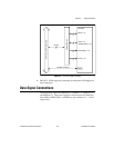
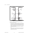
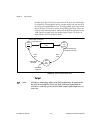
A good method for the 6533 device is to connect one fast Schottky
diode from +5V to each signal line, and another from the signal line to
ground. The +5V and ground connections should be low-impedance
connections. For example, if you make your +5V connection through a
long wire, back to the +5V pin of the 6533 device, add a capacitor to
your termination circuit to stabilize the +5V connection near the
Schottky diodes.
One suitable Shottky diode is the 1N5711, available from several
manufacturers. For more specialized use, you may be able to find diodes
packaged in higher densities appropriate to your application. For
example, the Central Semiconductor CMPSH-35 contains two diodes,
suitable for terminating one line. The California Micro Devices
PDN001 contains 32 diodes, suitable for terminating 16 lines.
You do not need to terminate the 6533 device input signals. The 6533
device contains onboard Schottky diode termination. Figure4-4 shows
the recommended transmission line terminations.


