


Chapter 2 Setup and Configuration
© National Instruments Corporation 2-11 NI CVS-1450 Series User Manual
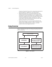
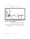
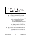
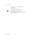
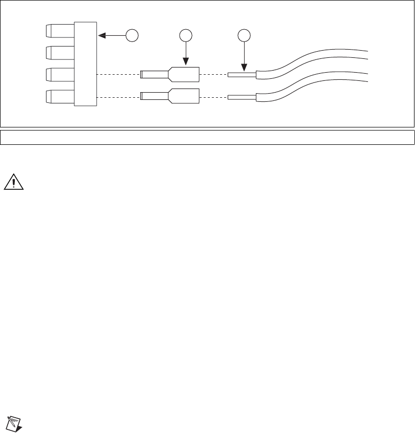
Figure 2-4. Wiring a Third-Party Power Supply to the 4-Position Power Connector
Caution
Do not connect the CVS-1450 device main power to a source other than
24 VDC ±10%. Do not connect the CVS-1450 device isolated power to a source less than
5 VDC or greater than 30 VDC. Doing so could damage the CVS-1450 device.
The CVS-1450 device ships with a 4-position power connector that plugs
directly into the power input connector on the CVS-1450 device. To wire
power to the 4-position connector, complete the following steps:
1. Wire the voltage output of the 24 VDC ±10% power supply to the main
voltage input, labeled V, on the 4-position connector.
2. Wire the common-mode signal (ground) output of the power supply
to the common-mode signal input, labeled C, on the 4-position
connector.
If you are using a separate power supply for the CVS-1450 device isolated
outputs, connect the voltage output on the power supply to the isolated
power (Viso) on the 4-position connector. Connect the common-mode
signal (ground) on the power supply to the isolated common-mode signal
(Ciso) on the connector.
Note If you do not require a separate power supply for the CVS-1450 device isolated
outputs, you can daisy-chain the V to the Viso and the C to the Ciso on the connector.
For information about grounding the CVS-1450 device chassis to earth
ground, refer to the Earth Ground Connection section of Chapter 3, LEDs,
DIP Switches, and Connectors.
1 4-Position Power Connector 2 Ferrule 3 Power Supply Wires
1
2
3