


Index
NI CVS-1450 Series User Manual I-4 ni.com
R
required hardware, 2-1
S
SAFE MODE DIP switch, 3-4
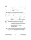
safety specifications, B-5
serial number, 5-2
serial port, connector (table), 3-6
setup
multiple CVS-1450s, 5-1
typical single-camera, 4-15
setup and configuration, 2-1
shutdown, disabling, 4-10
software
application, 1-4, 1-5
installing on development computer, 2-13
NI resources, D-1
NI-IMAQ for IEEE 1394 Cameras, 1-4
software choices, 1-4
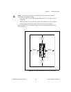
sourcing output device
wiring, 4-12
figure, 4-12
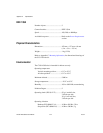
specifications
electromagnetic compatibility, B-5
environmental, B-4
memory, B-1
network, B-2
optically isolated
inputs, B-3
outputs, B-3
physical characteristics, B-4
power requirements, B-1
safety, B-5
TTL
inputs, B-2
outputs, B-2
STATUS LED, 3-2
error indications (table), A-4
subnet, 2-7, 5-2
support, technical, D-1
T
technical support, D-1
terminal block, 37-pin (table), 3-13
timed pulse output, initiating, 4-4
training and certification (NI resources), D-1
transmission line effects, 4-14
TRIG 0
cable, 3-12
connector (table), 3-6
TRIG 1
cable, 3-12
connector (table), 3-6
TRIG 2
cable, 3-12
connector (table), 3-6
trigger input lines, 4-3
trigger polarity, 4-5
troubleshooting
hardware, A-3
NI resources, D-1
software, A-1
STATUS LED error indications
(table), A-4
V
VGA
connector
figure, 3-9
table, 3-6
connector signals (table), 3-9
video formats, 1-3
Vision Builder AI
configuring IP address, 2-14
description, 1-5
image acquisition, 2-15
installing, 2-13