


Chapter 4 Digital I/O Functionality
NI CVS-1450 Series User Manual 4-16 ni.com
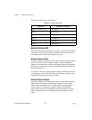
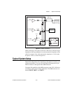
Table 4-5 summarizes a typical single-camera configuration.
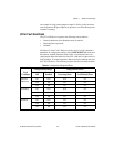
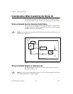
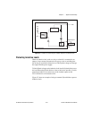
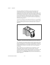
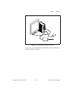
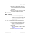
Figure 4-9 shows a typical single-camera setup.
Figure 4-9. Typical Single-Camera Setup
Table 4-5. Typical Single-Camera System Setup
Signal Name Signal Type Purpose
TRIG 0 Isolated input Trigger input from
proximity sensor or
external device
TRIG 1 Timed pulse TTL output Exposure start and
control signal to camera
TRIG 2 Timed pulse TTL output Strobe light control
1 Lighting Control Unit
2 Lighting Ring
3 Inspection Items
4 Proximity Sensor
NI 1454
Compact Vision System
1
2
3
4