


Chapter 3 LEDs, DIP Switches, and Connectors
© National Instruments Corporation 3-11 NI CVS-1450 Series User Manual
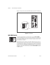
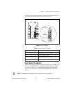
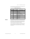
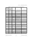
Table 3-4 lists pin numbers, signal names, and signal descriptions for the
9-pin COM1 connector on the CVS-1450 device.
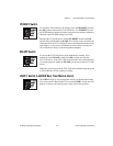
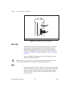
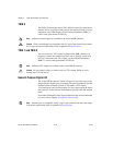
Ethernet
The Ethernet port on the CVS-1450 device provides connection between
the CVS-1450 device and the development computer, either directly or
through a network port. The CVS-1450 device automatically detects the
speed of the connection and configures itself accordingly.
If you are connecting the CVS-1450 device to the development computer
through a network port, use a standard Ethernet cable. To connect the
CVS-1450 device directly to the development computer, use an Ethernet
crossover cable.
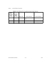
Table 3-4. COM1 Connector Signals
Pin
Number
Signal Name Signal Description
1 DCD Data Carrier Detect
2 RXD Receive Data
3 TXD Transmit Data
4 DTR Data Terminal Ready
5 C Common-mode signal of the
CVS-1450 device main power
6 DSR Data Set Ready
7 RTS Ready to Send
8 CTS Clear to Send
9 RI Ring Indicator