


Chapter 4 Digital I/O Functionality
© National Instruments Corporation 4-15 NI CVS-1450 Series User Manual
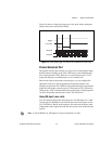
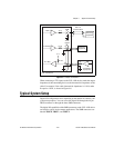
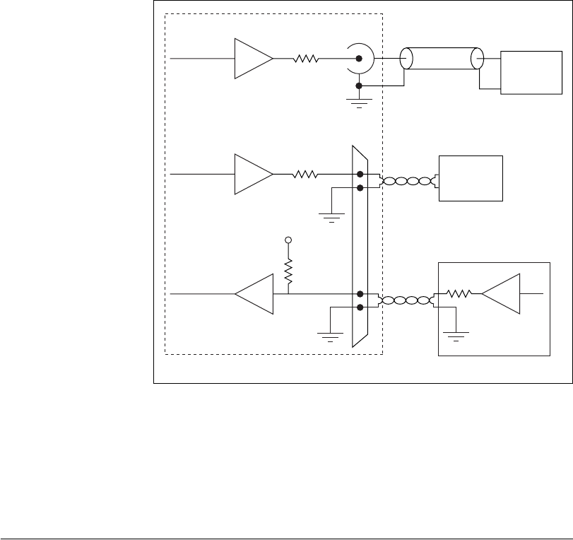
Figure 4-8. Example Connections
When connecting to TTL inputs on the CVS-1450 device, match the output
impedance of the transmitting device to the characteristic impedance of the
cable. For example, if the cable characteristic impedance is 118 Ω, make
R
s
equal to 118 Ω, as shown in Figure 4-8.
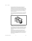
Typical System Setup
Digital I/O configuration varies depending on the number of cameras your
system setup requires. You can access the digital I/O through the 44-pin
DSUB connector or through the three SMB connectors.
The digital I/O capabilities of the SMB connectors on the CVS-1450 device
are ideal for typical single-camera applications. The SMB connectors are
labeled TRIG 0, TRIG 1, and TRIG 2.
TTL OUT(0)
Receiving
Equipment
TTL IN(0)
118 Ω
44-Pin
DSUB
3
2
16
17
62 kΩ
Transmitting
Equipment
R
S
TRIG 1
75 Ω
TRIG 1
SMB
RG-179
Coaxial Cable
+5 V
CVS-1450 device
Receiving
Equipment