


Chapter 3 LEDs, DIP Switches, and Connectors
NI CVS-1450 Series User Manual 3-6 ni.com
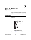
Connectors
This section describes the connectors on the CVS-1450 device and includes
pinouts and signal descriptions for each connector.
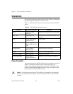
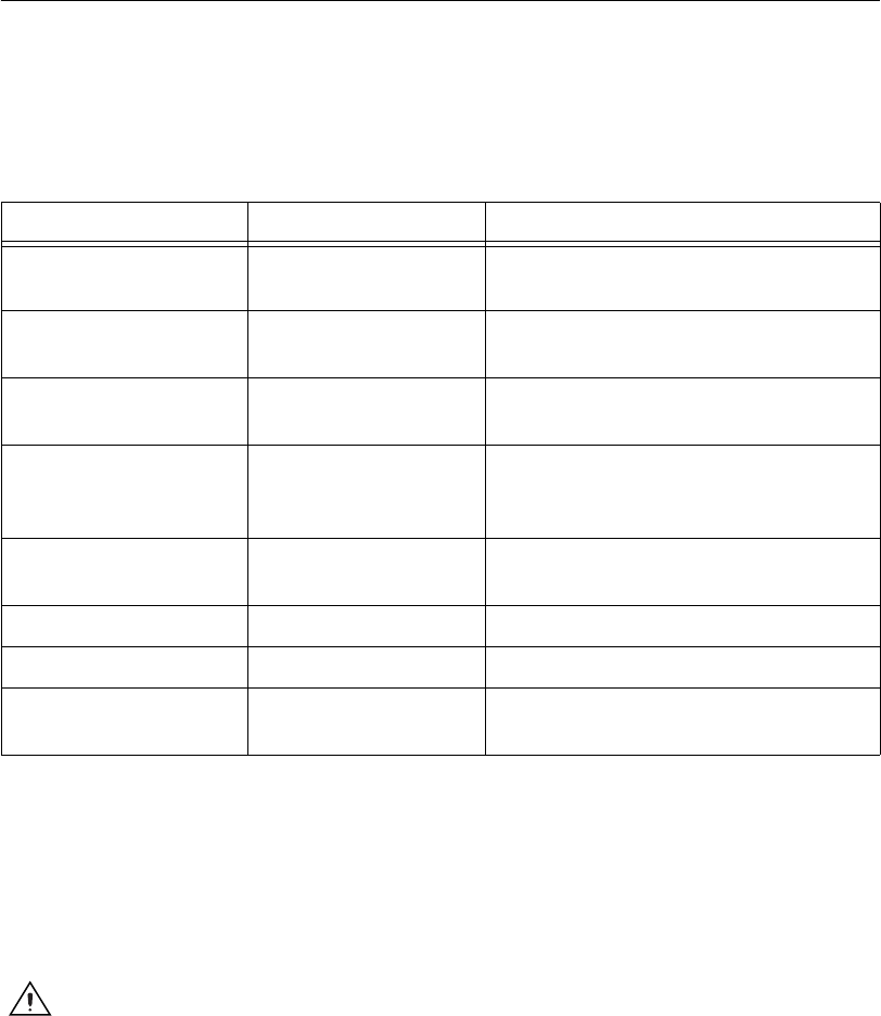
Table 3-1 summarizes the functions of the connectors on the CVS-1450
device.
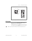
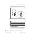
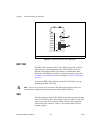
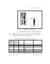
Power Connector
The power connector on the CVS-1450 device accommodates two power
supplies. The terminals labeled V and C provide the voltage and
common-mode signal for the main power of the CVS-1450 device. The
terminals labeled Viso and Ciso provide the voltage and common-mode
signal to power the isolated output circuitry.
Caution The isolation provided by the CVS-1450 device is intended to prevent ground
loops that could introduce noise into the system. This isolation does not provide safety
isolation.
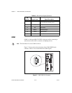
Table 3-1. CVS-1450 Device Connectors Overview
Peripheral External Connectors Function
Power 4-position power
connector
Main power and power for isolated outputs
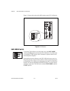
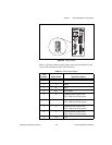
IEEE 1394a 6-pin IEEE 1394 Power and data connection to IEEE 1394
cameras
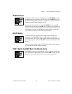
VGA 15-pin female DSUB
(standard VGA)
Video output
Serial 9-pin male DSUB
(standard RS-232 serial
port)
COM1
10/100 Ethernet RJ-45 (standard
Ethernet port)
Ethernet network connection
TRIG 0 SMB receptacle External isolated trigger input
TRIG 1 and TRIG 2 SMB receptacle External TTL output
Digital Input/Output 44-pin female
high-density DSUB
External TTL I/O; External isolated I/O