


© National Instruments Corporation 4-1 NI CVS-1450 Series User Manual
4
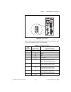
Digital I/O Functionality
This chapter describes the primary functions of the digital inputs and
outputs on the NI CVS-1450 device. This chapter also includes guidelines
for connecting the digital I/O and for setting up a typical CVS-1450 device.
Overview
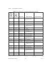
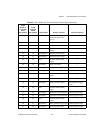
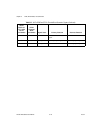
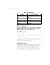
The digital I/O functions are accessible through 2 TTL inputs, 10 TTL
outputs, 13 isolated inputs, and 4 isolated outputs.
You can use input signals as triggers, product selection ports, or to read
quadrature encoders. Uses for output signals include controlling camera
reset and exposure, controlling strobe lighting, outputting inspection
results, or communicating with PLCs. You can also define the functions of
digital input and output signals.
For information about how to use the LabVIEW Real-Time Module to
implement specific digital I/O functions, refer to the application software
documentation and examples in the following locations:
•
Program Files\National Instruments\NI 1450 Series\Docs
• <
LabVIEW
>\examples\NI 1450
The NI 1450 Series Compact Vision System Digital I/O Help is available
for each example. This help file contains digital I/O reference information
and instructions for using the LabVIEW FPGA VIs.
Tip To quickly launch the digital I/O help from a LabVIEW example, press <F1>.
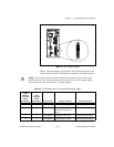
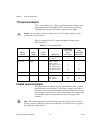
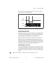
TTL and Isolated Inputs and Outputs
This section describes the TTL and Isolated I/O functions available on the
CVS-1450 device.