


Chapter 3 LEDs, DIP Switches, and Connectors
© National Instruments Corporation 3-7 NI CVS-1450 Series User Manual
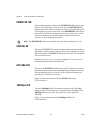
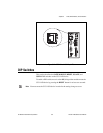
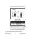
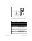
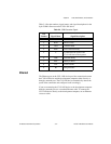
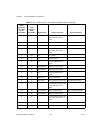
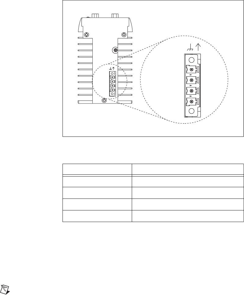
Figure 3-4 shows the power connector on the CVS-1450 device. Table 3-2
lists and describes each terminal on the power connector.
Figure 3-4. Power Connector
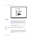
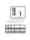
Earth Ground Connection
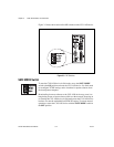
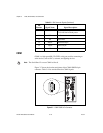
Some system setups may require using the grounding lug on the CVS-1450
device to connect the chassis to earth ground. Connecting the grounding
lug, shown in Figure 3-5, to earth ground connects the common-mode
signal of the main power to earth ground through the CVS-1450 device
chassis.
Note An earth ground connection does not connect Ciso to earth ground.
Table 3-2. Power Connector Terminals
Terminal Description
V Main power (24 VDC ±10%)
C Common-mode signal
Viso Isolated power (5 to 30 VDC)
Ciso Isolated common-mode signal
V
iso
(5-30 VDC)
C
C
iso
POWER
V
(24 VDC ±10%)
Viso
(5-30 VDC)
C
V
(24 VDC ±10%)
C
iso
POWER