


© National Instruments Corporation 3-1 NI CVS-1450 Series User Manual
3
LEDs, DIP Switches, and
Connectors
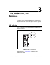
This chapter provides information about the location and functionality of
the LED indicators, DIP switches, and connectors on the NI CVS-1450
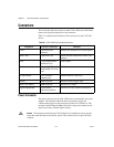
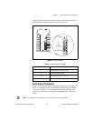
device. The Connectors section provides signal names and descriptions for
each connector.
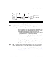
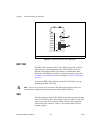
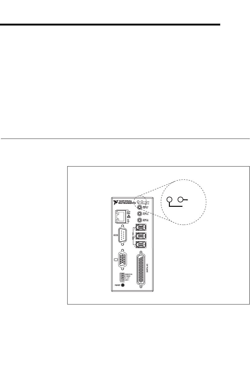
LED Indicators
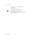
Figure 3-1 shows the location of the POWER OK and STATUS LEDs on
the CVS-1450 device.
Figure 3-1. POWER OK and STATUS LEDs
Refer to Appendix A, Troubleshooting, for information about
troubleshooting LEDs.
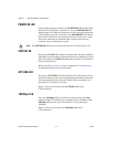
STATUS
POWER OK
NI 1454
Compact Vision System