


Chapter 3 LEDs, DIP Switches, and Connectors
© National Instruments Corporation 3-9 NI CVS-1450 Series User Manual
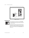
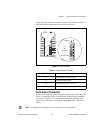
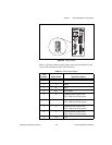
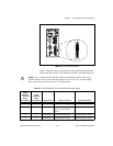
Figure 3-6. VGA Connector
Table 3-3 lists pin numbers, signal names, and signal descriptions for the
15-pin VGA connector on the CVS-1450 device.
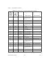
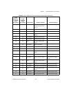
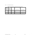
Table 3-3. VGA Connector Signals
Pin
Number
Signal Name Signal Description
1 R Red
2 G Green
3 B Blue
4 NC No Connect
5 C Common-mode signal of the
CVS-1450 device main power
6 C Common-mode signal of the
CVS-1450 device main power
7 C Common-mode signal of the
CVS-1450 device main power
8 C Common-mode signal of the
CVS-1450 device main power
9 +5 V +5 V
1611
51015
NI 1454
Compact Vision System