


Chapter 4 Digital I/O Functionality
NI CVS-1450 Series User Manual 4-14 ni.com
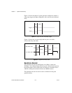
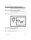
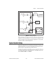
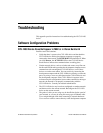
Figure 4-7. Example of Using an External Flyback Diode for Inductive Loads
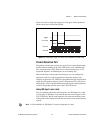
Transmission Line Effects
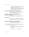
Transmission line effects can degrade the signals on the I/O cables and
cause instability. To minimize transmission line effects, use twisted-pair
wires with a characteristic impedance of 118 Ω to connect external signals
to the 44-pin I/O DSUB connector. Use a 75 Ω coaxial cable, such as
RG-179, to connect to the SMB connectors.
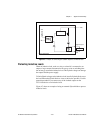
Figure 4-8 shows connections to the 44-pin DSUB connector and the
TRIG 0 SMB connector that minimize transmission line effects.
Digital
Output
Viso
Ciso
Vcc
CVS-1450 device
External
Flyback
Diode for
Inductive Loads
Load