


Chapter 3 LEDs, DIP Switches, and Connectors
NI CVS-1450 Series User Manual 3-12 ni.com
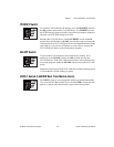
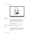
TRIG 0
The TRIG 0 isolated input on the CVS-1450 device provides connection to
external devices, such as proximity sensors and start/stop buttons. For easy
connection to the TRIG 0 input, use the National Instruments SMB 111
coaxial cable (part number 763422-01).
Note Additional isolated inputs are available on the 44-pin DSUB connector.
Caution These isolated inputs are compatible with 5 V logic if the external circuit meets
the voltage and current requirements listed in Appendix B, Specifications.
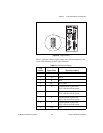
TRIG 1 and TRIG 2
You can use the two TTL outputs available on the SMB connectors for
triggering cameras and external interfaces, such as lighting control units.
For easy connection to the TTL outputs, use the National Instruments
SMB 111 coaxial cable (part number 763422-01).
Note Additional TTL outputs are available on the 44-pin DSUB connector.
Caution Do not connect voltage or current sources to TTL outputs. Doing so could
damage the CVS-1450 device.
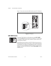
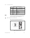
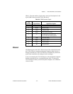
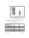
General-Purpose Digital I/O
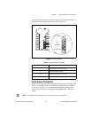
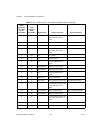
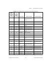
The 44-pin DSUB connector, shown in Figure 3-8, provides access to the
general-purpose digital inputs and outputs. The general-purpose digital I/O
available on this connector includes 2 TTL inputs, 8 TTL outputs,
12 isolated inputs, and 4 isolated outputs. For easy connection to the digital
I/O connector, use the National Instruments digital I/O cable and terminal
block.
For detailed information about digital I/O functionality and recommended
use cases, refer to Chapter 4, Digital I/O Functionality.
Note Isolated inputs are compatible with 5 V logic if the external circuit meets the voltage
and current requirements listed in Appendix B, Specifications.