


Chapter 3 LEDs, DIP Switches, and Connectors
© National Instruments Corporation 3-13 NI CVS-1450 Series User Manual
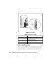
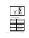
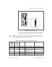
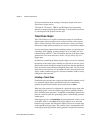
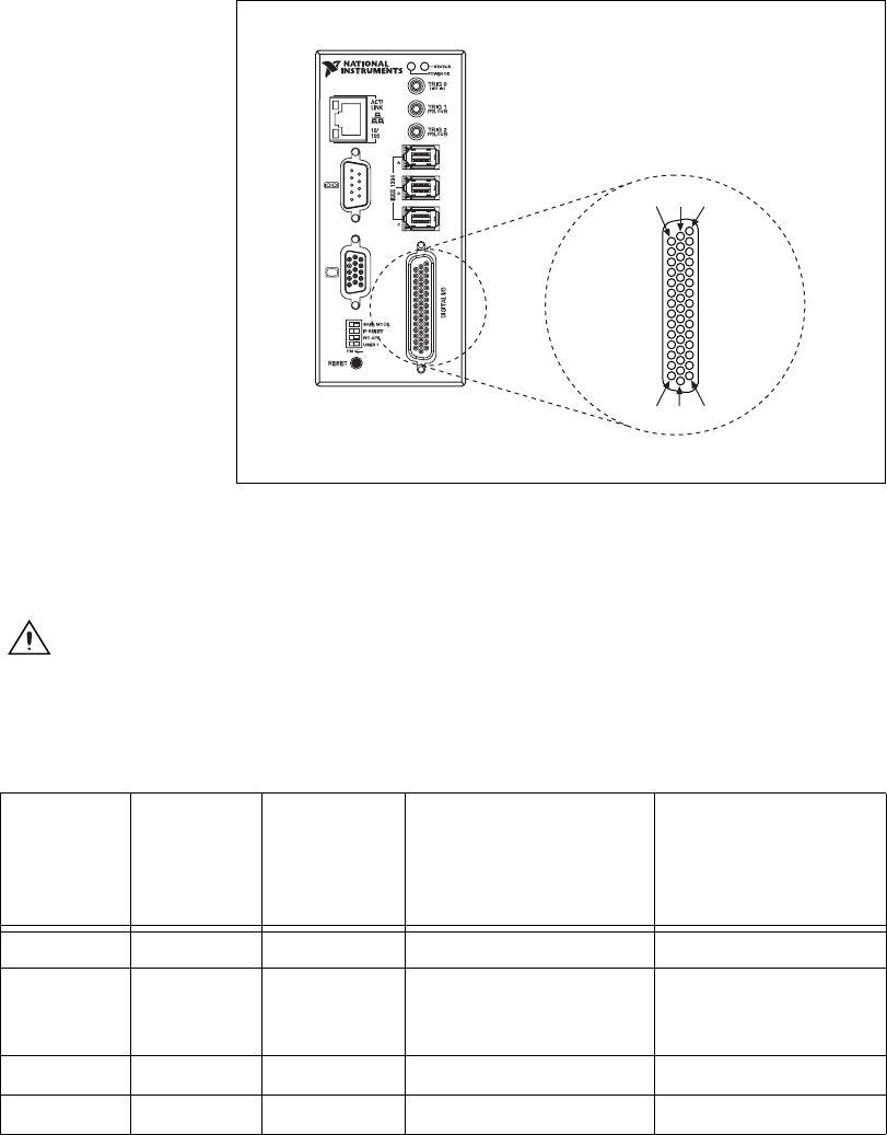
Figure 3-8. 44-Pin DSUB Connector
Table 3-5 lists pin numbers, signal names, and signal descriptions for the
44-pin connector on the CVS-1450 device and the 37-pin terminal block.
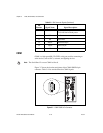
Caution Do not draw more than 500 mA combined from the Viso pins on the 44-pin
DSUB connector. Do not draw more than 100 mA from 24 V or 30 V isolated outputs.
Do not draw more than 50 mA from 5 V isolated outputs.
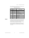
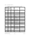
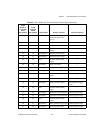
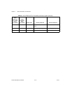
Table 3-5. 44-Pin DSUB and 37-Pin Terminal Block Connector Signals
44-Pin
DSUB on
CVS-1450
Device
Pin Number
37-Pin
Terminal
Block
Pin Number
Signal Name Primary Function Alternate Function
1 1 TTL Input 0 Pulse generator trigger input General-purpose input
2 3 C Common-mode signal of the
CVS-1450 device main
power
—
3 4 TTL Output 0 Watchdog timer output General-purpose output
4 5 TTL Output 1 Pulse generator output General-purpose output
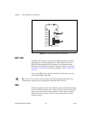
11631
153044
NI 1454
Compact Vision System