


Chapter 3 LEDs, DIP Switches, and Connectors
NI CVS-1450 Series User Manual 3-8 ni.com
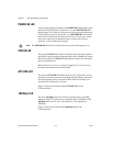
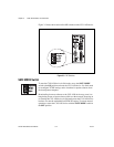
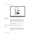
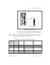
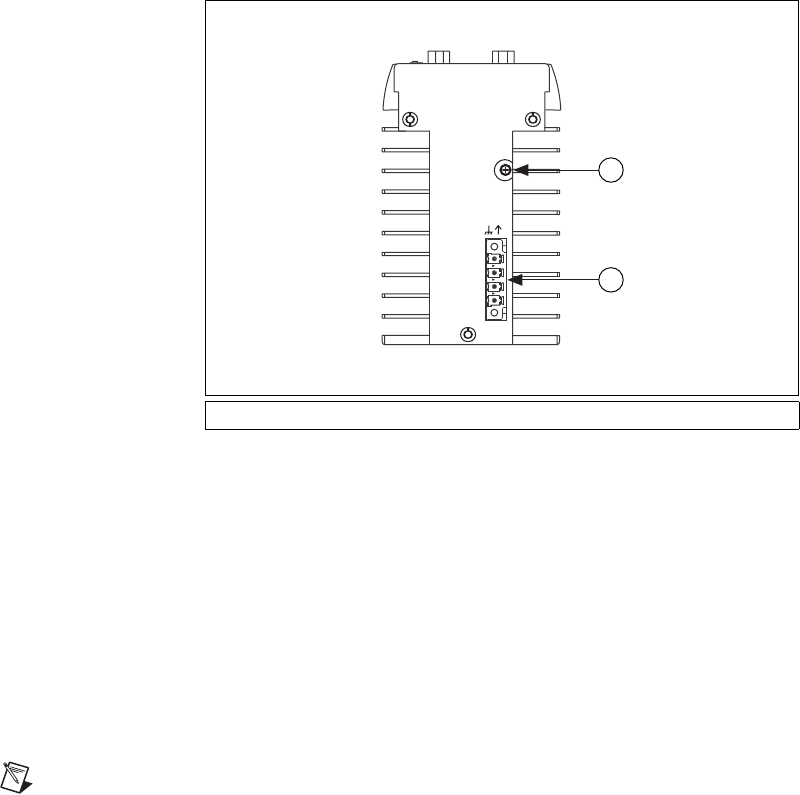
Figure 3-5. Grounding Lug on the CVS-1450 Device
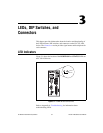
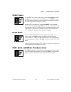
IEEE 1394
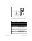
The IEEE 1394 connectors on the CVS-1450 device provide a reliable,
high-frequency connection between the CVS-1450 device and up to
three DCAM-compliant IEEE 1394 cameras. For information about
the amount of bandwidth available for connecting cameras, refer to the
Available Camera Bandwidth section of Chapter 1, NI CVS-1450 Series
Overview.
To access the IEEE 1394 connectors on the CVS-1450 device, use any
standard 6-pin IEEE 1394 cable.
Note You can use a 4-pin to 6-pin converter cable with cameras that have their own
external power supply and do not require power from the IEEE 1394 bus.
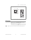
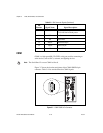
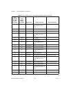
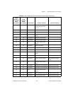
VGA
The VGA connector on the CVS-1450 device provides connection between
the CVS-1450 device and a VGA monitor. Use any standard 15-pin VGA
cable to access the VGA connector. Figure 3-6 shows the location and
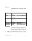
pinout of the VGA connector. Table 3-3 lists and describes the VGA
connector signals.
1 Grounding Lug 2 Power Connector
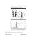
Viso
(5-30VDC)
C
V
(24VDC ±10%)
C
iso
POWER
1
2