


Chapter 4 Digital I/O Functionality
NI CVS-1450 Series User Manual 4-2 ni.com
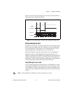
TTL Inputs and Outputs
TTL is a fast-switching, 5 V, digital, signaling standard commonly used
for applications that require high precision, such as camera triggering.
TTL inputs and outputs do not require a separate power supply.
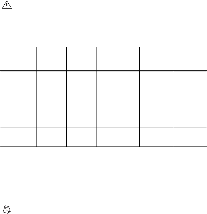
Caution Do not connect voltage or current sources to TTL outputs. Doing so could
damage the CVS-1450 device.
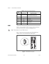
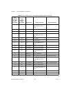
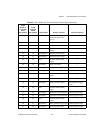
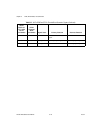
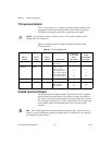
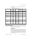
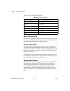
Table 4-1 summarizes the TTL inputs and outputs available on the
CVS-1450 device.
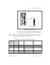
Isolated Inputs and Outputs
The isolated inputs and outputs on the CVS-1450 device have a separate
ground reference from the main CVS-1450 device supply, providing an
easy means to prevent ground loops that can introduce noise into a system.
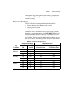
You can apply signals up to 30 V to the isolated inputs. The voltage swing
of the isolated outputs is determined by the Viso you supply on the
connector.
Note The isolated outputs have current-limiting protection circuitry. If this circuitry is
tripped, you can re-enable the outputs by restarting the CVS-1450 device or by toggling
the output state in the software.
Table 4-1. TTL Inputs and Outputs
Primary
Function
Input or
Output
Number
Available
Signal Names
44-Pin DSUB
on CVS-1450
Device
Pin Number
37-Pin
Terminal Block
Pin Number
Trigger Input 2 TTL Input 0
TTL Input 1
1
16
1
2
Timed Pulse Output 6 TRIG 1, Pulse 5
TRIG 2, Pulse 6
TTL Output 1, Pulse 1
TTL Output 2, Pulse 2
TTL Output 3, Pulse 3
TTL Output 4, Pulse 4
—
—
4
6
7
18
—
—
5
7
8
20
Watchdog Output 1 TTL Output 0 3 4
General-Purpose Output 3 TTL Output 5
TTL Output 6
TTL Output 7
19
21
22
21
23
24