


© National Instruments Corporation I-1 NI CVS-1450 Series User Manual
Index
Numerics
100 Mbps LED, 3-2
A
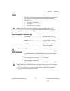
accessories, 2-2
application software
installing LabVIEW, 2-16
installing Vision Builder AI, 2-13
installing Vision Development
Module, 2-15
B
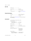
bandwidth, available (table), 1-3
C
cables
crossover, 2-2
digital I/O, 2-2
Ethernet crossover, 2-2
Ethernet standard, 2-2
SMB to BNC, 2-2
characteristic impedance, 4-15
calibration certificate (NI resources), D-2
camera
available bandwidth, 1-3
connecting to the CVS-1450, 2-8
digital camera specification, 1-1
video formats, 1-3
COM1, connector signals, 3-11
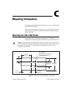
connecting multiple systems, subnet, 5-2
connectors, 3-6
COM1, 3-10
Ethernet, 3-11
IEEE 1394, 3-8
SMB, 3-6
TRIG 0, 3-12
TRIG 1, 3-12
TRIG 2, 3-12
VGA, 3-8
conventions used in the manual, v
CVS-1450 hardware
connecting multiple CVS-1450 systems
(figure), 5-1
connecting to development computer, 2-12
connectors (table), 3-6
D
DCAM specification, 1-1, G-1
Declaration of Conformity (NI resources), D-1
deployment, 5-1
development computer
connecting to CVS-1450, 2-13
installing application software, 2-13
installing LabVIEW, 2-16
installing Vision Development
Module, 2-15
diagnostic tools (NI resources), D-1
digital camera specification, 1-1
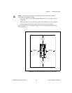
digital I/O
44-pin DSUB, 3-12
cable, D44, 3-12
connection considerations, 4-12
connector (table), 3-6
connector pinout (figure), 3-13
connector signals (table), 3-13
examples (LabVIEW Real-Time
Module), 4-1
external load, wiring, 4-12
general-purpose, 3-12