


Chapter 4 Digital I/O Functionality
© National Instruments Corporation 4-3 NI CVS-1450 Series User Manual
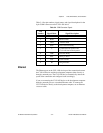
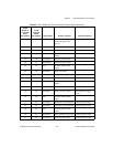
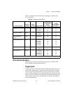
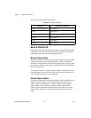
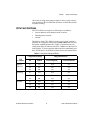
Table 4-2 summarizes the isolated inputs and outputs available on the
CVS-1450 device.
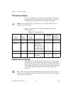
I/O for Normal Operation
The following sections describe I/O functions that are available on the
CVS-1450 device during normal operation.
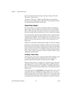
Trigger Inputs
Trigger inputs are available from both TTL inputs and isolated inputs. You
can use these trigger inputs to synchronize the CVS-1450 device with an
external event, such as the assertion of a signal generated by a proximity
sensor or a PLC to indicate that an inspection item is passing in front of the
camera. The CVS-1450 device uses this input to initiate a timed pulse that
can be used for camera control, lighting control, encoder pulse counting,
and result output timing.
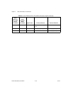
Table 4-2. Isolated Inputs and Outputs
Primary Function
Input or
Output
Number
Available
Signal Names
44-Pin DSUB
on CVS-1450
Device
Pin Number
37-Pin
Terminal Block
Pin Number
Trigger Input 3 TRIG 0
ISO Input 5
†
ISO Input 8
—
35
40
—
15
27
Quadrature Encoder Input 1 ISO Input 6
ISO Input 7
37
38
25
26
External Shutdown
Control
Input 1 ISO Input 11 44 31
Product Selection Port
†
Input 1 ISO Input 0
ISO Input 1
ISO Input 2
ISO Input 3
ISO Input 4
15
30
31
32
34
9
10
11
13
14
General-Purpose Input 2 ISO Input 9
ISO Input 10
41
43
29
30
General-Purpose Output 4 ISO Output 0
ISO Output 1
ISO Output 2
ISO Output 3
12
13
27
28
19
35
36
37
†
ISO Input 5 can also function as a latch for the product selection port.