


114
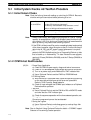
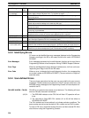
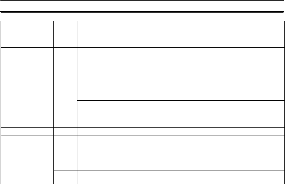
Message FALS
No.
Meaning and appropriate response
Power interruption
(no message)
None Power has been interrupted for at least 10 ms (2 ms for DC power types.) Check
power supply voltage and power lines. Try to power-up again.
MEMORY ERR
F1 AR 1308 ON: An unspecified bit area exists in the user program. Check the program
and correct errors.
AR 1309 ON: An error has occurred in reading or writing flash memory. Replace the
CPU Unit.
AR 1310 ON: A checksum error has occurred in read-only DM (DM 6144 to DM 6599).
Check and correct the settings in the read-only DM area.
AR 1311 ON: A checksum error has occurred in the PC Setup. Initialize all of the PC
Setup and reinput.
AR 1312 ON: A checksum error has occurred in the program. Check the program and
correct any errors detected.
AR 1314 ON: The internal capacitor can no longer back up data. Clear the error and
check/correct the contents of the data areas backed up by the capacitor.
NO END INST F0 END(01) is not written in the program. Write END(01) at the end of the program.
I/O BUS ERR C0 An error has occurred during data transfer between the CPU Unit and Expansion I/O
Unit. Check the Expansion I/O Unit’s connecting cable.
I/O UNIT OVER E1 Too many I/O Units have been connected. Check the I/O Unit configuration.
SYS FAIL FALS**
(** is 01 to 99 or 9F.)
01 to 99 A FALS(07) instruction has been executed in the program. Check the FALS number to
determine the conditions that caused execution, correct the cause, and clear the error.
9F The cycle time has exceeded the FALS 9F Cycle Time Monitoring Time (DM 6618).
Check the cycle time and adjust the Cycle Time Monitoring Time if necessary.
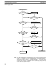
5-3-3 Identifying Errors
PC errors can be identified from error messages displayed on the Programming
Console, error flags in the SR or AR areas, and the error code in SR 25300 to
SR 25307.
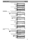
Error Messages Error messages generated by the self-diagnosis function can be read from a
Programming Console or host computer running SYSMAC Support Software.
Error Flags When the self-diagnosis function detects a hardware error, it will turn on the cor-
responding error flags in the SR and AR areas.
Error Code When an error is detected by the self-diagnosis function, the corresponding
error code is written to SR 25300 to SR 25307. (The error code is an 2-digit hex-
adecimal code.)
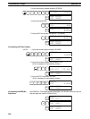
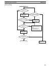
5-3-4 User-defined Errors
There are three instructions that the user can use to define his own errors or
messages. FAL(06) causes a non-fatal error, FAL(07) causes a fatal error, and
MSG(46) sends a message to the Programming Console or host computer con-
nected to the PC.
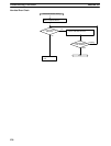
FAILURE ALARM – FAL(06) FAL(06) is an instruction that causes a non-fatal error. The following will occur
when an FAL(06) instruction is executed:
1, 2, 3... 1. The ERR/ALM indicator on the CPU Unit will flash. PC operation will con-
tinue.
2. The instruction’s 2-digit BCD FAL number (01 to 99) will be written to
SR 25300 to SR 25307.
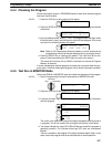
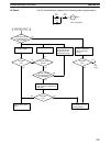
The FAL numbers can be set arbitrarily to indicate particular conditions. The
same number cannot be used as both an FAL number and an FALS number.
To clear an FAL error, correct the cause of the error and then execute FAL 00 or
clear the error using the Programming Console.
Self-diagnosis Functions
Section 5-3