


12
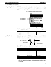
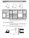
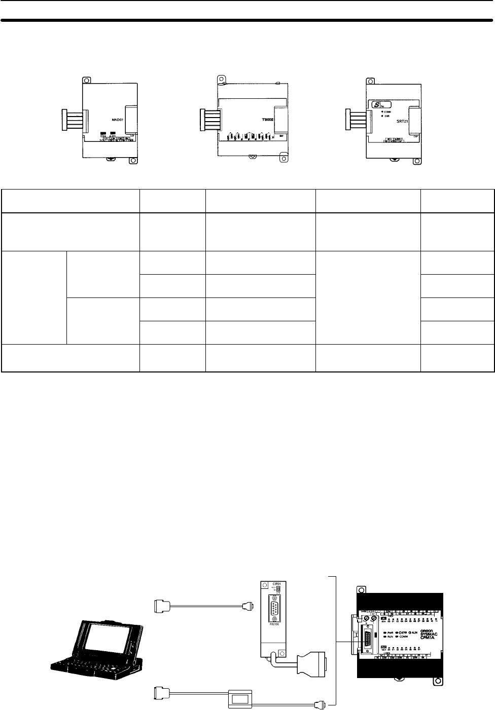
Expansion Units
Temperature Sensor Unit CompoBus/S I/O Link UnitAnalog I/O Unit
Unit Max. number
of Units
Inputs Outputs Model
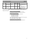
Analog I/O Unit
2 analog inputs (2 words)
1 analog output (1 word)
3 Units max. 2 analog inputs 1 analog output CPM1A-MAD01
Temperature
Sensor Unit
Thermocouple
inputs
3 Units max. 2 inputs (K, J)
---
CPM1A-TS001
1 Unit max.
(See note.)
4 inputs (K, J) CPM1A-TS002
Platinum
resistance
3 Units max. 2 inputs (Pt100, JPt100) CPM1A-TS101
thermometer
inputs
1 Unit max.
(See note.)
4 inputs (Pt100, JPt100) CPM1A-TS102
CompoBus/S I/O Link Unit
8 inputs and 8 outputs
3 Units max. 8 bits
(Inputs from the Master.)
8 bits
(Outputs to the Master.)
CPM1A-SRT21
Note Only one CPM1A-TS002/TS102 Temperature Sensor Unit can be connected to
the CPU Unit. If a CPM1A-TS002/102 is connected to the CPU Unit, only one
additional Expansion Unit (other than a CPM1A-TS002/102) or one Expansion
I/O Unit can be connected to the CPU Unit.
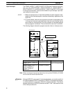
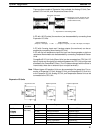
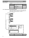
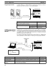
1-2-3 Host Link Communications
Host Link communications which allows up to 32 OMRON PCs to be controlled
from a host computer. The computer-PC connections can be made connectors
such as RS-232C and RS-422 Adapters.
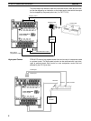
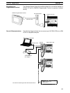
One-to-one Communications The following diagram shows the possible methods for a 1:1 connection
between a CPM1A and an IBM PC/AT or compatible computer.
IBM PC/AT or
compatible
RS-232C Cable
RS-232C Adapter
CQM1-CIF02
CPM1A CPU Unit
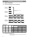
System Configuration
Section 1-2