


34
2-2-6 Communications Adapter Components
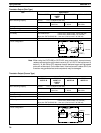
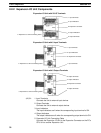
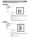
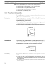
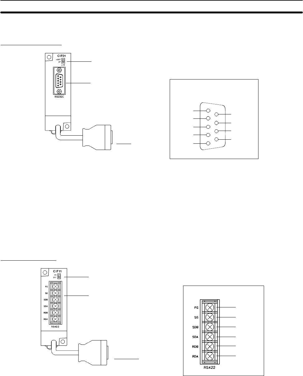
RS-232C Adapter
1. Mode Setting Switch
2. Connector
3. RS-232C port
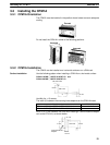
RS-232C Port Pin Allocation
1
2
3
4
5
6
7
8
9
FG
SD
RD
RTS
CTS
DCD
DSR
DTR
SG
1, 2, 3... 1. Mode Setting Switch
Set this switch to “HOST” when using a Host Link system to connect to a
personal computer. Set this switch to “NT” when connecting to a Program-
mable Terminal or PC for 1:1 PC Link.
2. Connector
Connects to the CPU Unit’s Peripheral Port.
3. RS-232C Port
Connects to the RS-232C cable from the other device such as a personal
computer, Peripheral Device, or Programmable Terminal.
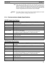
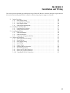
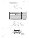
RS-422 Adapter
1. Termination Resistance Switch
2. Connector
3. RS-422 port
RS-422 Port Pin Allocation
FG
SG
SDB
SDA
RDB
RDA
1, 2, 3... 1. Termination Resistance Switch
Set the termination resistance switch to “ON” (upper side) for the Link
Adapters on both ends of the Host Link system and for the RS-422 Adapter.
2. Connector
Connects to the CPU Unit’s Peripheral Port.
3. RS-422 Port
Connects to the Host Link network.
Unit Components
Section 2-2