


23
Either switch the CPM1A to RUN or MONITOR mode, or turn off and on power to
the CPM1A after changing from a Programming Device any data that is backed
up in flash memory. This data includes the user program, read-only DM area
(DM 6144 to DM 6599), and the PC Setup (DM 6600 to DM 6655).
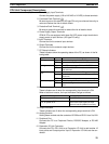
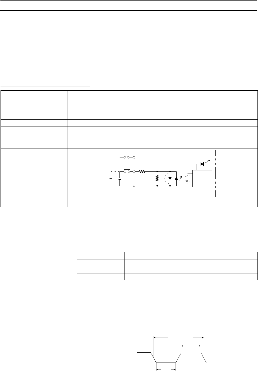
2-1-3 I/O Specifications
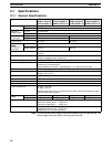
CPU Unit Input Specifications
Item Specification
Input voltage 24 VDC
+10%
/
–15%
Input impedance IN00000 to IN00002: 2 kΩ; other inputs: 4.7 kΩ
Input current IN00000 to IN00002: 12 mA typical; other inputs: 5 mA typical
ON voltage 14.4 VDC min.
OFF voltage 5.0 VDC max.
ON delay 1 to 128 ms max. Default: 8 ms (see note.)
OFF delay 1 to 128 ms max. Default: 8 ms (see note.)
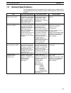
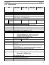
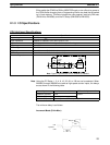
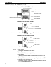
Circuit configuration
IN
COM
4.7 kΩ
(2 kΩ)
Input
LED
Internal
Circuits
820 Ω
(510 Ω)
Note Figures in parentheses are for IN00000 to IN00002.
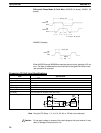
IN
Note Using the PC Setup, 1, 2, 4, 8, 16, 32, 64, or 128 ms can be selected. When
IN00000 through IN00002 are used as high-speed counter inputs, the delays
are as shown in the following table.
Input Increment mode Differential phase mode
IN00000 (A-phase) 5 kHz
2.5 kHz
IN00001 (B-phase) Normal input
IN00002 (Z-phase) ON: 100 µs min.; OFF delay: 500 µs min.
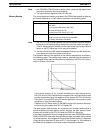
The minimum delay is as follows.
Increment Mode (5 kHz Max.)
200 µs min.
90 µs
min.
ON
OFF
90 µs
min.
A phase
Specifications Section 2-1