


!
59
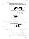
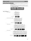
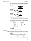
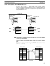
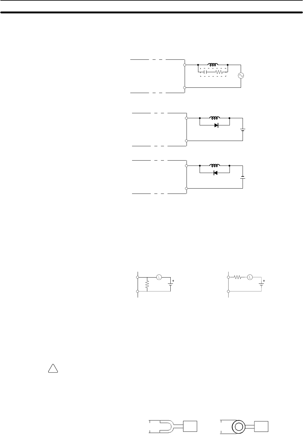
Inductive Loads
When connecting an inductive load to an input, connect a surge protector or
diode in parallel with the load.
The surge protector’s components should have the following ratings:
OUT
COM
CPM1A
Surge protector
Relay Output
OUT
COM
CPM1A
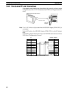
Diode
Relay Output
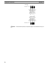
Transistor Output
(Sink Type)
OUT
COM
CPM1A
Diode
Relay Output
Transistor Output
(Source Type)
The diode should satisfy the following requirements:
Peak reverse-breakdown voltage must be at least 3 times the load voltage.
Average rectified current must be 1 A.
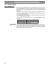
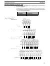
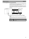
Inrush Current Considerations
When switching a load with a high inrush current in the CPM1A relay output or
transistor output model, such as an incandescent lamp, suppress the inrush cur-
rent as shown below.
OUT
COM
R
OUT
COM
R
Countermeasure 1
Providing a dark current of
approx. one-third of the rated
value through an incandescent
lamp
Countermeasure 2
Providing a limiting resistor
Fuse Insertion
The CPM1A with transistor output may burn if the load is short-circuited, there-
fore, insert a protective fuse in series to the load.
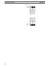
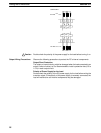
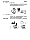
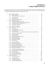
Crimp Connectors
Caution Always use crimp connectors for the CPM1A’s power lines and I/O lines or else
use a solid wire (instead of a stranded wire). Do not connect bare stranded wires
directly to terminals. Bare stranded wires connected directly to the terminal can
cause a fire.
Use M3 terminal screws and tighten the screws securely (0.5 N S m).
6.2 mm max. 6.2 mm max.
Fork terminal Ring terminal
The recommended wire size for solid wires is 0.4 to 1.2 mm (AWG26 to AWG18).
Wiring and Connections
Section 3-4